Chrysler Le Baron, Dodge Dynasty, Plymouth Acclaim. Manual — part 83
not to allow dirt to enter or grease to leave the boot
cavity. The clamp must be removed and discarded be-
fore the rod can be inserted. After venting, install a
new Service Clamp. (See Boots Install section at the
end of this group for details).
HUB NUT INSTALL
The front wheel hub nuts use a lock and cotter pin
to maintain proper wheel bearing preload and pre-
vent the nut from backing off. Install the assembly
as follows:
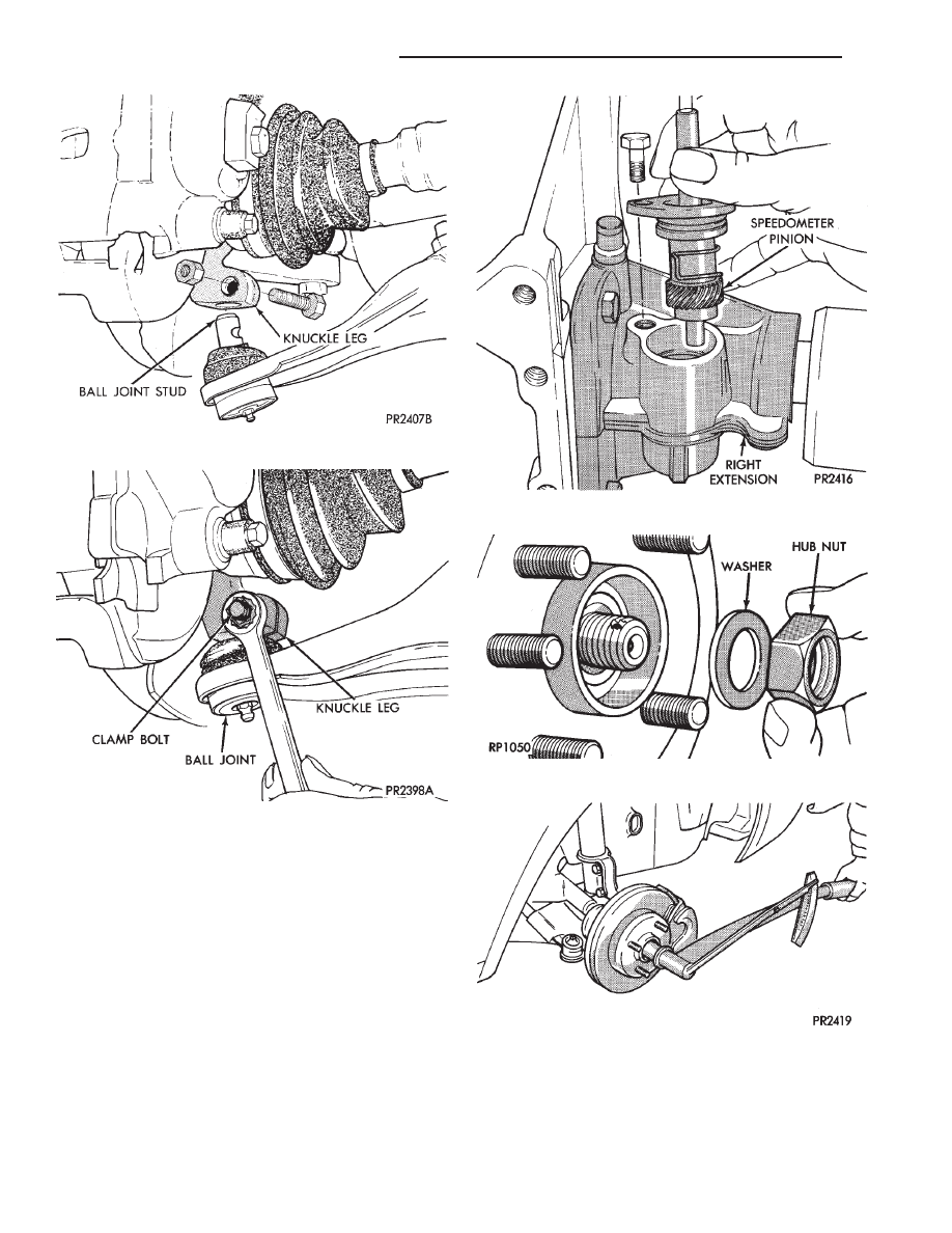
(1) Install washer and hub nut after cleaning for-
eign matter from threads (Fig. 18).
(2) With brakes applied, tighten hub nut to 245
N
Im (180 ft. lbs.) torque (Fig. 19).
(3) Install lock, spring washer and new cotter
pin. Wrap cotter pin prongs tightly around nut lock
(Fig. 20).
(4) Install wheel and tire assembly. Tighten wheel
nuts to 129 N
Im (95 ft. lbs.) torque (Figs. 21).
Fig. 15 Install Knuckle Assembly on Ball Joint Stud
Fig. 16 Tighten Clamp Bolt
Fig. 17 Install Speedometer Pinion
Fig. 18 Install Washer & Hub Nut
Fig. 19 Tighten Hub Nut
2 - 30
SUSPENSION AND DRIVESHAFTS
Ä

DRIVESHAFT RECONDITIONING PROCEDURE
Driveshaft reconditioning and/or boot replacement
for all front wheel drive vehicles is essentially the same
per C/V joint.
Note: that lubricant requirements and quanti-
ties are different for Inner Joints than for Outer
Joints, and type being serviced. Use only the
recommended lubricants.
See (Fig. 1) for the exploded view of the front drive
shaft components and there location in the assembly.
Driveshaft requirements are different for vari-
ous vehicle models, engines, and transaxles, and
often change from one model year to the next.
Driveshaft parts will be different to accommodate
this. Therefore, when replacing parts, be sure to use
only those specified in the service parts catalog. For
the exact model year, model, engine, transaxle, and
type being serviced.
Fig. 1 Driveshaft Components
Fig. 21 Install Wheel And Tire Assembly
Fig. 20 Install Spring Washer, Nut Lock, & New Cot-
ter Pin
Ä
SUSPENSION AND DRIVESHAFTS
2 - 31
INNER C/V JOINT
DISASSEMBLE
With driveshaft assembly removed from vehicle,
identify unit type (See Fig. 2 under Driveshafts Iden-
tification).
(1) Remove the boot clamps and pull back the boot
to gain access to the tripod retention system, which
prevents accidental separation from the C/V joint
housing.
CAUTION: When removing the housing from the tri-
pod, hold the rollers in place on the trunnion studs
to prevent the rollers and needle bearings from fall-
ing away. After the tripod is out of the housing se-
cure the rollers in place with tape (Fig. 4).
(2) Depending on the type of C/V joint assembly,
separate the tripod from the housing as follows:
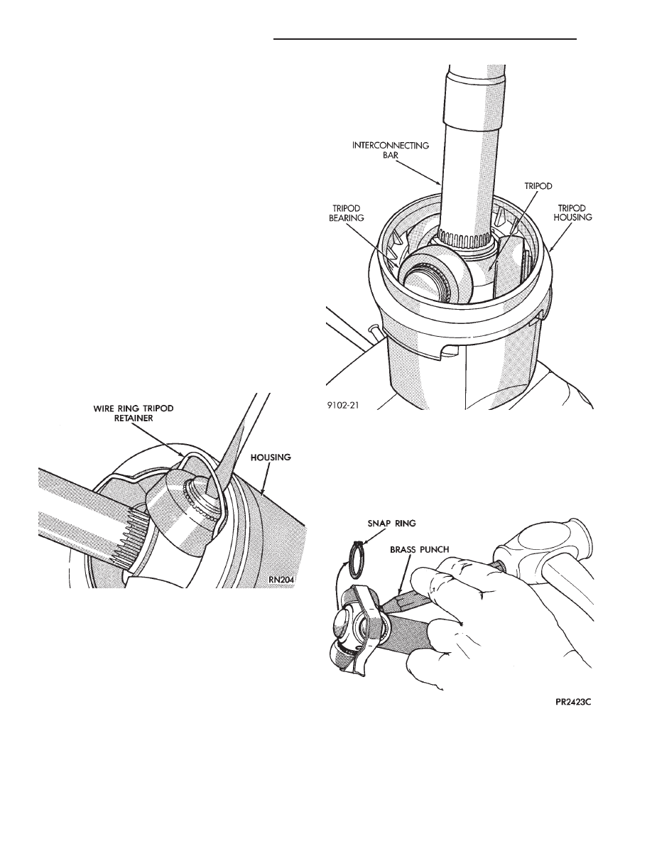
S.S.G. Utilizes a wire ring tripod retainer which
expands into a groove around the top of the housing.
Use a flathead screwdriver to pry the wire ring out
of the groove and slide the tripod from the housing
(Fig. 2). Do not mangle or destroy retainer dur-
ing disassembly.
G.K.N. The retention system on this assembly is a
integral part of the plastic collar on the inside of the
C/V joint housing. Clamp the stub shaft of the C/V
joint housing in a vise, use protective caps on
jaws of vise to prevent damage to stub shaft.
Hold the interconnecting shaft on an angle, while
gently pulling on the shaft until one of the tripod
bearings is free of the retaining collar. Continue
holding the interconnecting shaft on an angle and
gently pull on the shaft until all rollers are free of
the retaining collar. See (Fig. 3).
TRIPOD REMOVAL FROM INTERCONNECTING
BAR
S.S.G. Remove the snap ring from the shaft end groove.
Remove the tripod by hand or by tapping the body with a
brass punch (Fig. 4).
G.K.N. To remove the tripod from the interconnecting bar.
(1) Expand the stop ring behind the tripod and
slide it back along the shaft (Fig. 5).
Fig. 2 Separate Tripod From Housing S.S.G.
Fig. 3 Separate Tripod From Housing G.K.N.
Fig. 4 Remove Snap Ring then Tripod
2 - 32
SUSPENSION AND DRIVESHAFTS
Ä

(2) Slide the tripod back along the shaft, either by
hand or by tapping the body with a brass drift. This
will expose the circlip on the end of the interconnect-
ing bar.
(3) Remove the circlip from the end of intercon-
necting bar (Fig. 6).
(4) Remove the tripod from the interconnecting
bar. It is not necessary to remove the stop ring from
the interconnecting bar unless the bar is being re-
placed (Fig. 7).
S.S.G. AND G.K.N. WITH SINGLE RING TRIPOD
RETENTION.
Remove the tripod assembly to interconnecting
shaft retaining snap ring from the interconnecting
shaft end groove (Fig. 8). Remove the tripod assem-
bly from the interconnecting shaft by hand or by tap-
ping the body of the tripod assembly with a brass
punch (Fig. 9).
G.K.N. WITH DOUBLE RING TRIPOD RETENTION.
(1) Expand and remove the outer tripod assembly
to interconnecting shaft, retaining snap ring (Fig.
10).
(2) Remove the tripod assembly from the intercon-
necting shaft. Tripod can be removed either by hand
or by tapping the tripod body with a brass drift (Fig.
4). Do not hit the outer tripod bearings in an attempt
to remove tripod assembly from interconnecting
shaft.
(3) Remove inner tripod assembly to interconnect-
ing shaft, retaining snap ring from interconnecting
shaft (Fig. 11).
Fig. 5 Removing Stop Ring (G.K.N.)
Fig. 6 Removing Circlip
Fig. 7 Tripod Removed From The Interconnecting
Bar
Fig. 8 Outer Tripod Retaining Snap Ring Removal
Ä
SUSPENSION AND DRIVESHAFTS
2 - 33
Нет комментариевНе стесняйтесь поделиться с нами вашим ценным мнением.
Текст