Chrysler Le Baron, Dodge Dynasty, Plymouth Acclaim. Manual — part 340
EXTERIOR LAMPS—AY-BODY
INDEX
page
page
Center High Mounted Stop Lamp Bulb (CHMSL)
Cornering Lamp or Bulb—AY/C-P-Body
Front Side Marker Bulb—AY/C-P-Body
Front Side Marker Lamp—AY/C-P-Body
. . . . . . . . . . . . . . . . . . . . . . . 22
. . . . . . . . . . . . . . . . . . . . . . 22
. . . . . . . . . . . . . . . . . . . . . . . . . . . . . 22
License Plate Lamp or Bulb—AY/C-P-Body
Park, Turn Signal Lamp or Bulb—AY/C-P-Body
. . . . . . . . . . . . . . . . . . . . . . . . . . . 22
Tail, Stop, Turn Signal, Side Marker and Back-Up
. . . . . . . . . . . . . . 24
GENERAL INFORMATION
To service exterior lamps on AY/C-S-Body, refer to
procedures covered in Exterior Lamps—AC-Body sec-
tion. AC/C-S-Body uses the same lamps as AY/C-S-
Body.
HEADLAMPS
Conventional and halogen sealed beams are inter-
changeable, It is not recommended that they be
mixed. The lens, filament and reflector of sealed
beams are molded into one unit.
HEADLAMP DIAGNOSIS
For headlamp diagnosis, refer to the headlamp di-
agnosis chart at the beginning of this Group. Refer to
Wiring Diagrams manual for circuit and component
locations.
SEALED BEAM
REMOVAL
(1) Turn the headlight switch ON.
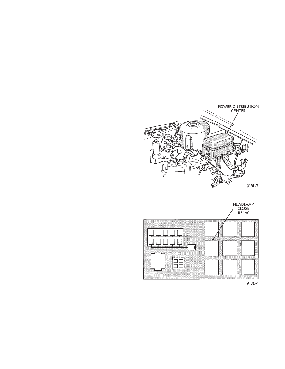
(2) Open the hood and locate the power distribu-
tion center forward of the left front suspension tower
(Fig. 1). Remove the cover.
(3) Remove the headlamp close relay (Fig. 2) to
prevent the headlamp doors from closing.
(4) Turn the headlight switch OFF.
(5) Remove screws from headlamp bezel and re-
move bezel, if equipped.
Do not disturb the headlamp adjusting screws.
(6) Remove screws from interior retaining ring
(Fig. 3), and remove ring.
(7) Separate sealed beam from seat and disconnect
wire connector.
INSTALLATION
Reverse the preceding operation.
PARK, TURN SIGNAL LAMP OR BULB—AY/C-P-
BODY
REMOVAL
(1) Open the headlamp doors.
(2) Remove push-in fasteners holding lower park
and turn signal lamp shield to grille opening panel
(Fig. 4).
(3) Remove screws holding park and turn signal
lamp grille opening panel (Fig. 5).
(4) Remove sockets from lamp and pull bulbs from
sockets if bulbs replacement is required (Fig. 6).
Fig. 1 Power Distribution Center
Fig. 2 Headlamp Close Relay
8L - 22
LAMPS
Ä

INSTALLATION
Reverse the preceding operation.
FRONT SIDE MARKER BULB—AY/C-P-BODY
REMOVAL
(1) Raise vehicle.
(2) Reach over the top of cornering lamp (Fig. 7)
and remove bulb/socket (Fig. 8).
INSTALLATION
Reverse the preceding operation.
FRONT SIDE MARKER LAMP—AY/C-P-BODY
REMOVAL (FIG. 7)
(1) Remove the cornering lamp retaining nuts, and
remove cornering lamp.
(2) Remove the four nuts retaining the bumper
trim moulding to the body.
(3) Remove bumper trim moulding.
(4) Remove side marker lamp.
INSTALLATION
Reverse the preceding operation.
Fig. 3 Sealed Beam Replacement—Typical
Fig. 4 Turn Signal Lamp Shield
Fig. 5 Turn Signal Lamp Mounting Screws
Fig. 6 Turn Signal Lamp
Fig. 7 Bumper Trim Moulding Nuts—AY/C-P-Body
Ä
LAMPS
8L - 23

CORNERING LAMP OR BULB—AY/C-P-BODY
REMOVAL (FIG. 8)
(1) Raise vehicle.
(2) Remove bulb.
(3) To remove lamp assembly, remove the two re-
taining nuts.
INSTALLATION
Reverse the preceding operation.
TAIL, STOP, TURN SIGNAL, SIDE MARKER AND
BACK-UP LAMP OR BULB—AY/C-P-BODY
REMOVAL (FIG. 9)
(1) Open the trunk lid and remove the tail panel
trim cover attaching screws and position the trim
cover away from the tail panel.
(2) Disconnect rear end lamp wire connector and
push the harness grommet outward through the tail
panel.
(3) Remove rear lamp assembly attaching screws
and separate the lamp assembly from the body.
(4) Remove bulbs from lamp assembly.
INSTALLATION
Reverse the preceding operation.
LICENSE PLATE LAMP OR BULB—AY/C-P-BODY
REMOVAL
(1) Remove the two screws retaining the lamp to
the bumper guard.
(2) Remove the bulb from the socket assembly.
INSTALLATION
Reverse the preceding operation.
CENTER HIGH MOUNTED STOP LAMP BULB
(CHMSL)
REMOVAL AND INSTALLATION
(1) Open deck lid.
(2) From under the parcel shelf, rotate socket
counterclockwise, and pull the CHMSL socket and
bulb from the lamp.
(3) Pull bulb from the socket.
INSTALLATION
Reverse the preceding operation.
CENTER HIGH MOUNTED STOP LAMP
REMOVAL (FIG. 10)
(1) Remove parcel shelf trim cover. Refer to Group
23, Body.
(2) Remove two CHMSL attaching screws and sep-
arate the lamp from the parcel shelf.
INSTALLATION
Reverse the preceding operation.
Fig. 8 Cornering Lamp—AY/C-P-Body
Fig. 9 Rear End Lighting—AY/C-P-Body
Fig. 10 Center High Mounted Stop Lamp—Typical
8L - 24
LAMPS
Ä
EXTERIOR LAMP SYSTEMS
INDEX
page
page
Daytime Running Lamp—Canada Only
. . . . . . . . . . . . . . 26
Lamp Outage Module—All Except AA-Body
. . . . . . . . . . . . . . . . . . . . . 25
. . . . . . . . . . . . . . . . . . . . . . . . . 25
LAMP OUTAGE SYSTEM
Diagnostics and component relationships for AC,
AG, AJ or AY-Bodies can be found in the Body Di-
agnostic Procedures Manual, Electronic Vehicle In-
formation Center (EVIC) section.
For circuit and component locations on AA-body,
refer to the Wiring Diagrams Manual.
LAMP OUTAGE MODULE—ALL EXCEPT AA-BODY
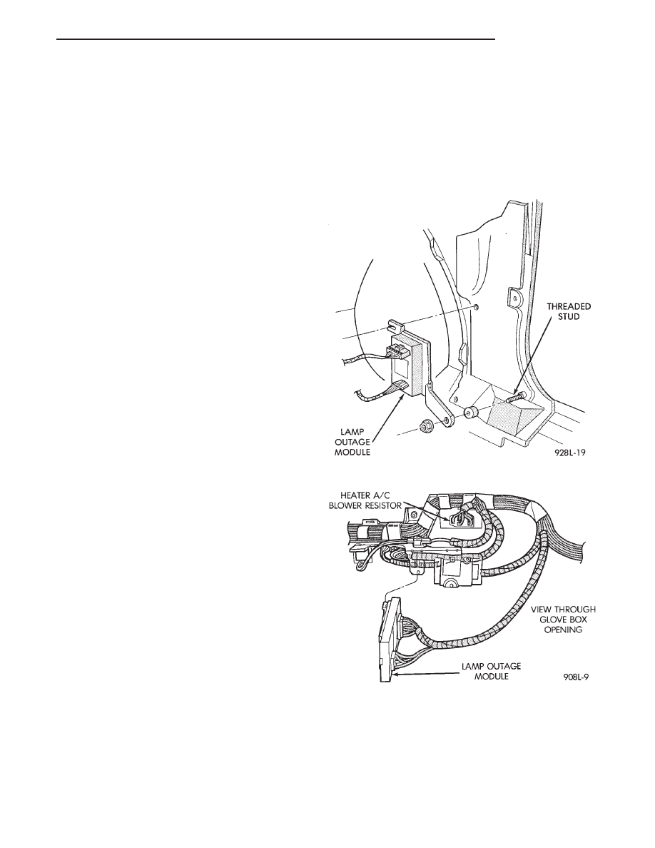
REMOVAL
(1) Remove battery negative cable.
(2) Remove the glove box assembly. Refer to Group
8E, Instrument Panel.
(3) Disconnect the wire connector from the lamp
outage module.
(4) Remove lamp outage module attaching screw
and remove the module from the vehicle (Figs. 1, 2
or 3).
INSTALLATION
Reverse the preceding operation.
LAMP OUTAGE MODULE—AA-BODY
REMOVAL (FIG. 1)
(1) Remove battery negative cable
(2) Disconnect the wire connectors from the lamp
outage module.
(3) Remove screws or clip holding lamp outage
module to instrument panel above glove compart-
ment (Fig. 1, 2 or 3).
(4) Separate lamp outage module from vehicle.
INSTALLATION
Reverse the preceding operation.
DAYTIME RUNNING LAMP—CANADA ONLY
DIAGNOSIS
For circuit and component locations refer to the
Wiring Diagrams manual.
REMOVAL (FIG. 4)
(1) Remove the left front inner fender shield, if
equipped, and disconnect the wire connector from the
day time running lamp module.
(2) Remove daytime running lamp module attach-
ing screws and separate the module from the inner
fender support.
INSTALLATION
Reverse the preceding operation.
Fig. 1 Lamp Outage Module—AA-Body
Fig. 2 Lamp Outage Module—AG and AJ-Body
Ä
LAMPS
8L - 25
Нет комментариевНе стесняйтесь поделиться с нами вашим ценным мнением.
Текст