Chrysler Le Baron, Dodge Dynasty, Plymouth Acclaim. Manual — part 594
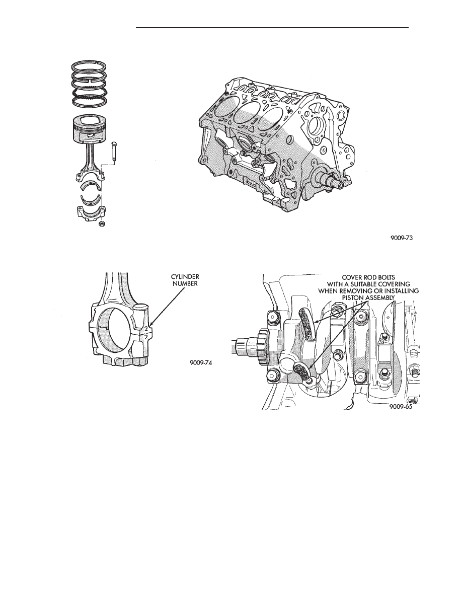
CYLINDER BLOCK, PISTON AND CONNECTING ROD ASSEMBLY SERVICE
CYLINDER BLOCK
PISTON—REMOVAL
(1) Remove top ridge of cylinder bores with a reliable
ridge reamer before removing pistons from cylinder
block. Be sure to keep tops of pistons covered
during this operation. Pistons and connecting
rods must be removed from top of cylinder block.
When removing piston and connecting rod as-
semblies from the engine, rotate crankshaft so
that each connecting rod is centered in cylinder
bore.
(2) Inspect connecting rods and connecting rod caps
for cylinder identification. Identify them if necessary.
(Fig. 2)
(3) Remove connecting rod cap. Install connecting
rod bolt protectors on connecting rod bolts (Fig. 3).
Push each piston and rod assembly out of cylinder
bore.
Be careful not to nick crankshaft journals.
(4) After removal, install bearing cap on the mat-
ing rod.
CLEANING AND INSPECTION
(1) Clean cylinder block thoroughly and check all
core hole plugs for evidence of leaking.
(2) If new core plugs are installed, see Engine Core
Oil and Cam Plugs.
(3) Examine block for cracks or fractures.
Fig. 1 Cylinder Block, Piston and Connecting Rod Assembly
Fig. 2 Identify Connecting Rod to Cylinder
Fig. 3 Connecting Rod Protectors
9 - 114
3.3/3.8L ENGINE
Ä

CYLINDER BORE INSPECTION
The cylinder walls should be checked for out- of-
round and taper with Tool C-119 (Fig. 4). If the cylinder
walls are badly scuffed or scored, the cylinder block
should be replaced.
Measure the cylinder bore at three levels in direc-
tions A and B (Fig. 4). Top measurement should be
12mm (.50 inch) down and bottom measurement
should be 12mm (.50 inch.) up from bottom of bore.
Refer to (Fig. 5) for specifications.
FINISHED PISTONS
All pistons are machined to the same weight in
grams, to maintain piston balance. For cylinder bores
which have been honed, new pistons and connecting
rod assemblies are available for service.
FITTING PISTONS
Piston and cylinder wall must be clean and dry.
Piston diameter should be measured 90 degrees to
piston pin at size location shown in (Fig. 6). Cylinder
bores should be measured halfway down the cylinder
bore and transverse to the engine crankshaft center
line shown in (Fig. 4). Refer to (Fig. 5) for specifica-
tions.
Pistons and cylinder bores should be measured
at normal room temperature, 70°F (21°C)
PISTON PINS
The piston pin rotates in the piston only, and is
retained by the press interference fit of the piston pin
in the connecting rod. The piston pin is not to be
removed damage to the piston may result.
FITTING RINGS
(1) Wipe cylinder bore clean. Insert ring and push
down with piston to ensure it is square in bore. The
ring gap measurement must be made with the ring
positioning at least 12mm (.50 inch) from bottom of
cylinder bore. Check gap with feeler gauge (Fig. 7).
Fig. 5 Cylinder Bore and Piston Specifications
Fig. 6 Piston Measurements
Fig. 7 Check Gap on Piston Rings
Fig. 4 Checking Cylinder Bore Size
Ä
3.3/3.8L ENGINE
9 - 115
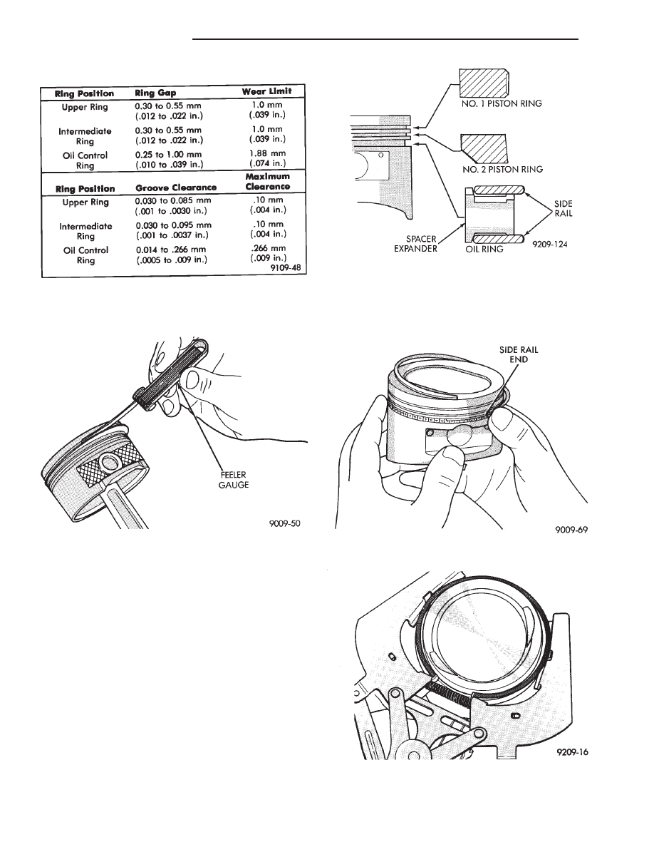
Refer to specifications (Fig. 8).
(2) Check piston ring to groove clearance: (Fig. 9).
Refer to specification (Fig. 8).
PISTON RINGS—INSTALLATION
(1) The No. 1 and No. 2 piston rings have a differ-
ent cross section. Install rings with manufacturers
I.D. mark facing up, to the top of the piston (Fig. 10).
CAUTION: Install piston rings in the following or-
der:
(a) Oil ring expander.
(b) Upper oil ring side rail.
(c) Lower oil ring side rail.
(d) No. 2 Intermediate piston ring.
(e) No. 1 Upper piston ring.
(2) Install the side rail by placing one end between
the piston ring groove and the expander. Hold end
firmly and press down the portion to be installed un-
til side rail is in position. Do not use a piston ring
expander. (Fig. 11).
(3) Install upper side rail first and then the lower
side rail.
(4) Install No. 2 piston ring and then No. 1 piston
ring (Fig. 12).
Fig. 8 Piston Ring Specifications
Fig. 9 Measuring Piston Ring Side Clearance
Fig. 10 Piston Ring Installation
Fig. 11 Installing Side Rail
Fig. 12 Installing Upper and Intermediate Rings
9 - 116
3.3/3.8L ENGINE
Ä
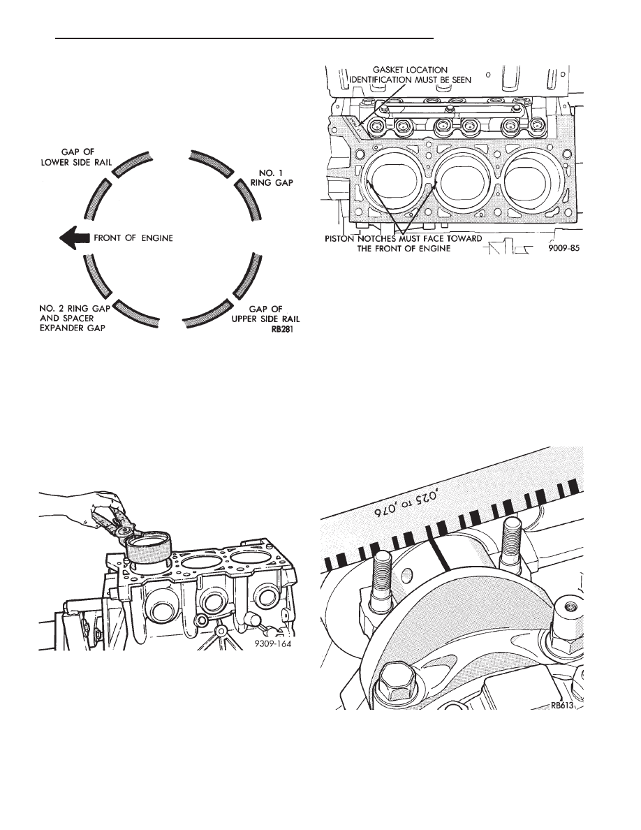
(5) Position piston ring end gaps as shown in (Fig.
13).
(6) Position oil ring expander gap at least 45° from
the side rail gaps but not on the piston pin center or on
the thrust direction. Staggering ring gap is important
for oil control.
INSTALLING PISTON AND CONNECTING ROD AS-
SEMBLY
(1) Before installing pistons and connecting rod as-
semblies into the bore, besure that compression ring
gaps are staggered so that neither is in line with oil
ring rail gap.
(2) Before installing the ring compressor, make sure
the oil ring expander ends are butted and the rail gaps
located as shown in (Fig. 14).
(3) Immerse the piston head and rings in clean
engine oil, slide the ring compressor, over the piston
and tighten with the special wrench. Be sure position
of rings does not change during this operation.
(4) Install connecting rod bolt protectors on rod
bolts. (Fig. 3)
(5) Rotate crankshaft so that the connecting rod
journal is on the center of the cylinder bore. Insert
rod and piston into cylinder bore and guide rod over
the crankshaft journal.
(6) Tap the piston down in cylinder bore, using a
hammer handle. At the same time, guide connecting
rod into position on connecting rod journal.
(7) The notch or groove on top of piston must be
pointing toward front of engine (Fig. 15).
(8) Install rod caps. Install nuts on cleaned and
oiled rod bolts and tighten nuts to 54 N
Im (40 ft. lb.)
Plus 1/4 turn.
Fig. 15 Piston I.D. Notches
Fig. 16 Checking Connecting Rod Bearing
Clearance
Fig. 13 Piston Ring End Gap Position
Fig. 14 Installing Piston
Ä
3.3/3.8L ENGINE
9 - 117
Нет комментариевНе стесняйтесь поделиться с нами вашим ценным мнением.
Текст