Chrysler Le Baron, Dodge Dynasty, Plymouth Acclaim. Manual — part 40
FUEL SYSTEM PRESSURE RELEASE PROCEDURE
WARNING: RELEASE FUEL SYSTEM PRESSURE
BEFORE SERVICING FUEL SYSTEM COMPONENTS.
WHEN
SERVICING
FLEXIBLE
FUEL
VEHICLES,
WEAR METHANOL RESISTANT GLOVES AND EYE
PROTECTION AND AVOID BREATHING FUMES. DO
NOT ALLOW METHANOL/GASOLINE MIXTURES TO
CONTACT SKIN. SERVICE VEHICLES IN WELL VEN-
TILATED AREAS AND AVOID IGNITION SOURCES.
NEVER SMOKE WHILE SERVICING THE VEHICLE.
(1) Disconnect negative cable from battery.
(2) Remove fuel filler cap.
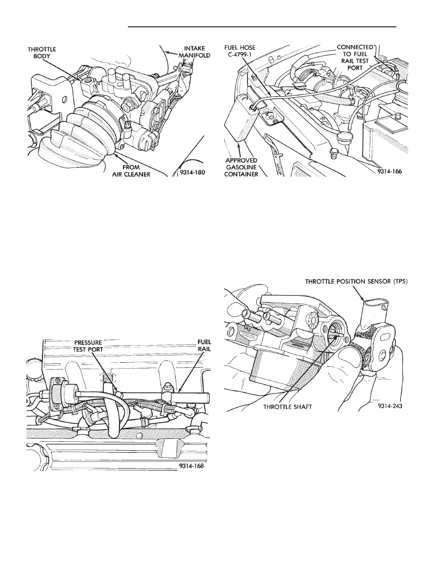
(3) Remove the protective cap from the fuel pres-
sure test port on the fuel rail (Fig. 2).
(4) Place the open end of fuel pressure release
hose, tool number C-4799-1, into a container ap-
proved for methanol/gasoline mixtures. Connect the
other end of hose C-4799-1 to the fuel pressure test
port (Fig. 3). Fuel pressure will bleed off through the
hose
into
the
gasoline
container.
Fuel
gauge
C-4799-A contains hose C-4799-1.
THROTTLE POSITION SENSOR (TPS)
REMOVAL
(1) Disconnect the negative cable from the battery.
(2) Disconnect harness connector from throttle po-
sition sensor (Fig. 4).
(3) Remove
throttle
position
sensor
mounting
screws.
(4) Lift throttle position sensor off throttle shaft.
INSTALLATION
(1) Install throttle position sensor on throttle shaft.
Install mounting screws. Tighten screws to 2 N
Im (17
in. lbs.) torque.
(2) Attach harness connector to sensor.
(3) Connect negative cable to negative post of the
battery.
IDLE AIR CONTROL MOTOR
REMOVAL
(1) Disconnect negative cable from battery.
(2) Disconnect harness connector from idle air con-
trol motor (Fig. 5).
Fig. 1 Throttle Body
Fig. 2 Fuel Pressure Test Port
Fig. 3 Releasing Fuel Pressure
Fig. 4 Servicing Throttle Position Sensor
14 - 78
FUEL SYSTEMS
Ä
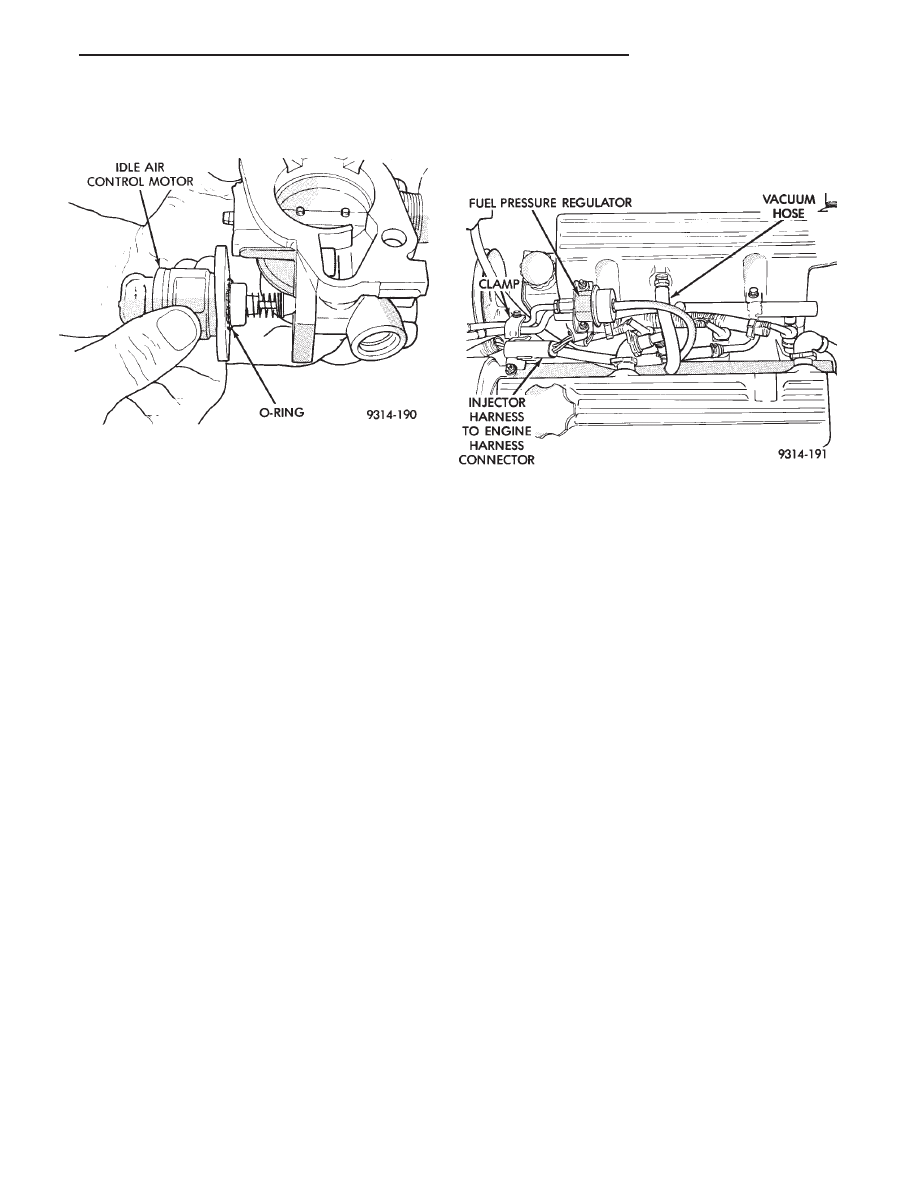
(3) Remove idle air control motor mounting screws.
(4) Remove idle air control motor from throttle
body (make certain that the O-ring is on motor).
INSTALLATION
(1) New idle air control motors have a new O-ring
installed on them. If pintle measures more than 1
inch (25 mm) it must be retracted. Use the IDLE
AIR CONTROL MOTOR OPEN/CLOSE mode of the
DRBII scan tool (battery must be reconnected for this
operation).
(2) Carefully place idle air control motor into
throttle body.
(3) Install 2 mounting screws. Tighten screws to 2
N
Im (17 in. lbs.) torque.
(4) Connect harness connector to motor.
(5) Connect negative cable to battery.
THROTTLE BODY REMOVAL
(1) Disconnect negative cable from battery.
(2) Remove clamp from air hose. Remove hose (Fig.
1).
(3) Remove accelerator cable.
(4) Disconnect idle air control motor and throttle
position sensor (TPS) electrical connectors.
(5) Remove throttle body mounting nuts.
(6) Remove throttle body and gasket.
(7) Reverse the above procedures for installation.
FUEL INJECTOR RAIL ASSEMBLY
WARNING: RELEASE FUEL SYSTEM PRESSURE
BEFORE SERVICING FUEL SYSTEM COMPONENTS.
WHEN
SERVICING
FLEXIBLE
FUEL
VEHICLES,
WEAR METHANOL RESISTANT GLOVES AND EYE
PROTECTION AND AVOID BREATHING FUMES. DO
NOT ALLOW METHANOL/GASOLINE MIXTURES TO
CONTACT SKIN. SERVICE VEHICLES IN WELL VEN-
TILATED AREAS AND AVOID IGNITION SOURCES.
NEVER SMOKE WHILE SERVICING THE VEHICLE.
REMOVAL
(1) Perform fuel system pressure release procedure.
(2) Disconnect negative cable from battery.
(3) Disconnect the fuel injector harness connector
from the engine harness (Fig. 6).
(4) Remove the quick connect fittings from the
chassis fuel tubes. Refer to Quick Connect Fittings in
the Fuel Delivery section of this group.
(5) Disconnect the vacuum hose from the top of the
intake manifold (Fig. 6).
(6) Disconnect vacuum hose from the pressure reg-
ulator (Fig. 6).
(7) Remove screw from the fuel tube clamp (Fig.
6).
(8) Remove fuel rail mounting screws.
(9) Pull up on the injector rail. The injectors will
pull straight out of the ports. Do not damage the in-
jector O-rings.
(10) Remove fuel rail assembly from vehicle. Do
not remove fuel injectors until fuel rail assembly has
been completely removed from vehicle.
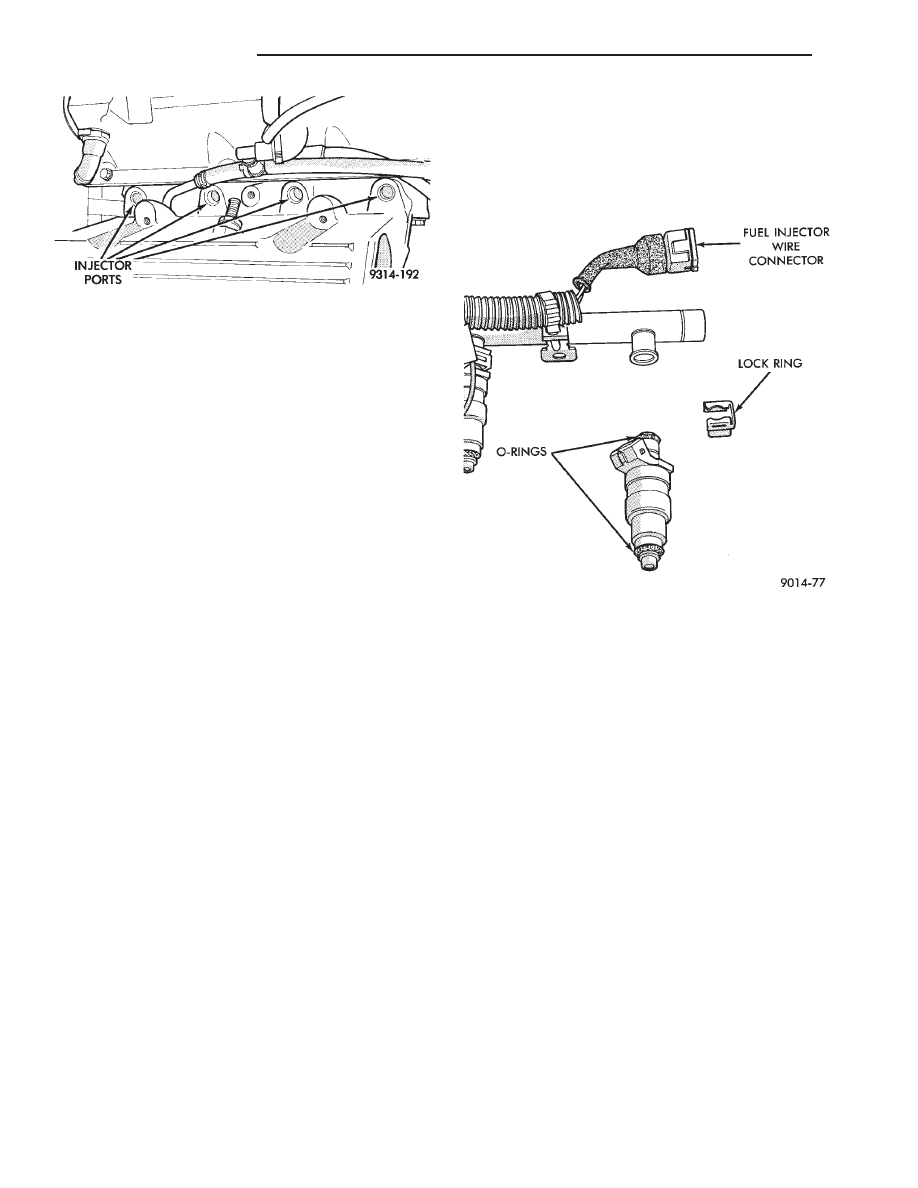
(11) Plug or cover intake manifold injector ports to
prevent dirt from entering the openings (Fig. 7).
INSTALLATION
WARNING: FUEL RAILS, INJECTORS AND PRES-
SURE REGULATORS DESIGNED FOR GASOLINE
ONLY VEHICLES CANNOT BE USED ON FLEXIBLE
FUEL AA-BODY VEHICLES. WHEN SERVICING THE
FUEL SYSTEM OF A FLEXIBLE FUEL VEHICLE,
ONLY USE ORIGINAL EQUIPMENT OR EQUIVA-
LENT REPLACEMENT COMPONENTS.
(1) Ensure injectors are seated into the receiver
cup on the fuel rail with the lock ring in place.
(2) Attach harness connectors to injectors. Fasten
the harness into wiring clips.
Fig. 5 Servicing Idle Air Control Motor
Fig. 6 Injector Harness and Engine Harness
Connection
Ä
FUEL SYSTEMS
14 - 79
(3) Ensure the injector holes are clean and all plugs
have been removed.
(4) Lubricate the injector O-rings with a drop of
clean engine oil to ease installation.
(5) Install the injector assembly into their holes.
Install mounting screws. Fuel rail assembly must be
drawn into the intake manifold evenly making sure
each injector enters its own hole. Once all injectors are
seated, tighten bolts to 23 N
Im (200 in. lbs) torque.
(6) Connect vacuum hose to fuel pressure regulator.
(7) Close fuel tube clip around fuel tubes and install
fastener.
(8) Lubricate the ends of the chassis fuel tubes with
a light coating of clean 30 weight engine oil. Connect
fuel supply and return hoses to chassis fuel tube
assembly. Pull back on the quick connect fittings to
ensure complete insertion. Refer to Quick Connect
Fittings in the Fuel Delivery section of this group.
(9) Connect vacuum hose intake manifold nipple.
(10) Connect negative cable to battery.
CAUTION: When using the ASD Fuel System Test, the
Auto Shutdown (ASD) Relay remains energized for
either 7 minutes, until the test is stopped, or until the
ignition switch is turned to the Off position.
(11) With the DRBII scan tool, use the ASD Fuel
System Test to pressurize system and check for leaks.
FUEL INJECTOR
The fuel rail must be removed to service the injec-
tors. Refer to Fuel Injector Rail Assembly in this
section.
REMOVAL
WARNING: RELEASE FUEL SYSTEM PRESSURE BE-
FORE SERVICING FUEL SYSTEM COMPONENTS.
WHEN
SERVICING
FLEXIBLE
FUEL
VEHICLES,
WEAR METHANOL RESISTANT GLOVES AND EYE
PROTECTION AND AVOID BREATHING FUMES. DO
NOT ALLOW METHANOL/GASOLINE MIXTURES TO
CONTACT SKIN. SERVICE VEHICLES IN WELL VEN-
TILATED AREAS AND AVOID IGNITION SOURCES.
NEVER SMOKE WHILE SERVICING THE VEHICLE.
(1) Disconnect electrical connector from injector
(Fig. 8).
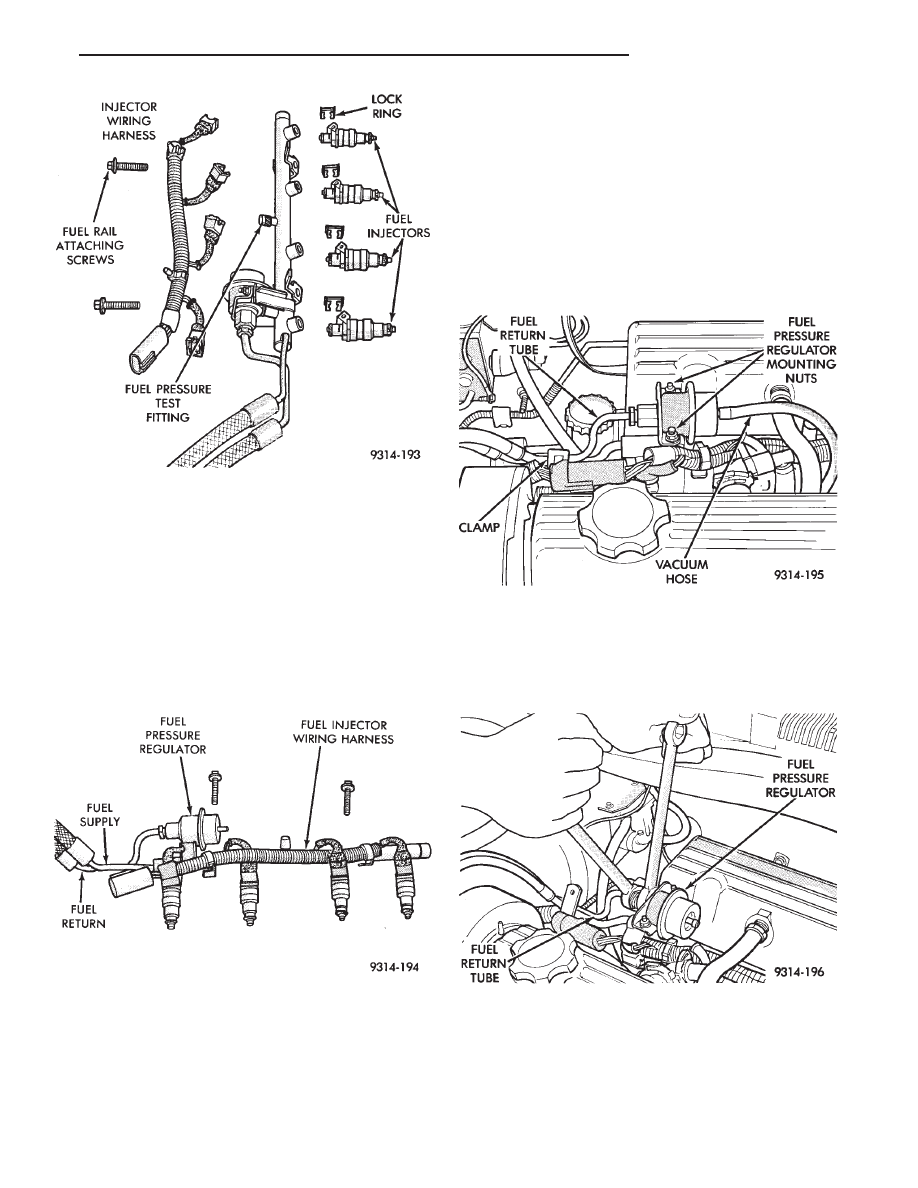
(2) Position fuel rail assembly so that the fuel injec-
tors are easily accessible (Fig. 9).
(3) Remove injector lock ring from fuel rail and
injector. Pull injector straight out of fuel rail receiver
cup.
(4) Check injector O-ring for damage. Replace dam-
aged O-rings. If injector is reused, install a protective
cap on the injector tip to prevent damage.
(5) Repeat steps for remaining injectors.
INSTALLATION
WARNING:
FUEL
INJECTORS
AND
INJECTOR
O-RINGS DESIGNED FOR GASOLINE ONLY VE-
HICLES CANNOT BE USED ON FLEXIBLE FUEL AA-
BODY VEHICLES. WHEN SERVICING THE FUEL SYS-
TEM OF A FLEXIBLE FUEL VEHICLE, ONLY USE
ORIGINAL EQUIPMENT OR EQUIVALENT REPLACE-
MENT COMPONENTS.
Fig. 7 Fuel Injector Ports
Fig. 8 Servicing Fuel Injectors
14 - 80
FUEL SYSTEMS
Ä
(1) Before installing an injector, lubricate O-ring
with a drop of clean engine oil.
(2) Being careful not to damage the O-ring, install
injector top end into fuel rail receiver cup.
(3) Install injector lock ring by sliding open end
into slot of the injector and onto the receiver cup
ridge into the side slots of ring (Fig. 8).
(4) Repeat steps for remaining injectors.
(5) Install injector wiring harness to injectors and
fasten into wiring clips (Fig. 10).
FUEL PRESSURE REGULATOR
WARNING: RELEASE FUEL SYSTEM PRESSURE
BEFORE SERVICING FUEL SYSTEM COMPONENTS.
WHEN
SERVICING
FLEXIBLE
FUEL
VEHICLES,
WEAR METHANOL RESISTANT GLOVES AND EYE
PROTECTION AND AVOID BREATHING FUMES. DO
NOT ALLOW METHANOL/GASOLINE MIXTURES TO
CONTACT SKIN. SERVICE VEHICLES IN WELL VEN-
TILATED AREAS AND AVOID IGNITION SOURCES.
NEVER SMOKE WHILE SERVICING THE VEHICLE.
REMOVAL
(1) Perform fuel system pressure release procedure.
(2) Disconnect negative cable from battery.
(3) Disconnect vacuum hose from fuel pressure reg-
ulator (Fig. 11).
Place a shop towel under fuel pressure regula-
tor to absorb any fuel spillage.
(4) Use 2 tubing wrenches, to loosen the line nut
on the fuel return tube (Fig. 12).
(5) Remove fuel pressure regulator mounting nuts
(Fig. 11).
(6) Lift pressure regulator up out of fuel rail (Fig.
13). Ensure the O-ring and spacer were removed
with the regulator. Discard O-Ring.
Fig. 9 Fuel Rail and Injector Assembly
Fig. 10 Fuel Rail Assembly
Fig. 11 Servicing Fuel Pressure Regulator
Fig. 12 Removing Fuel Return Tube
Ä
FUEL SYSTEMS
14 - 81
Нет комментариевНе стесняйтесь поделиться с нами вашим ценным мнением.
Текст