Chrysler Le Baron, Dodge Dynasty, Plymouth Acclaim. Manual — part 195
Shaft seal replacement should be done on the
bench. Never use any old parts of the shaft seal
assembly. Rebuild the complete assembly.
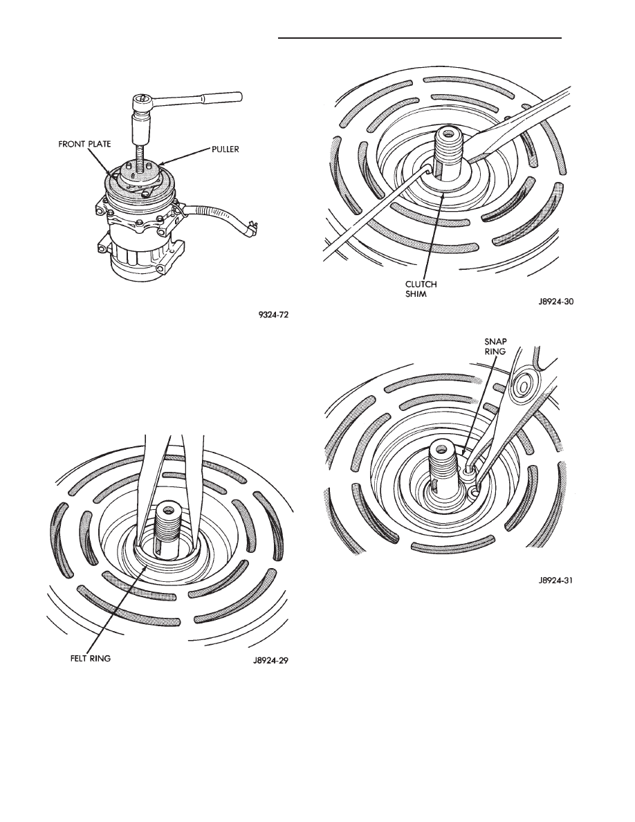
(4) Using either of the snap ring tools, insert the tool
points into the 2 holes of the felt ring metal retainer.
Lift the felt ring out (Fig. 3).
(5) Remove the clutch shim. Use O-ring hook and a
small screwdriver to prevent shim from binding on
shaft (Fig. 4).
(6) Remove shaft seal seat retaining snap ring with
pinch type snap ring pliers (Fig. 5).
(7) Remove the shaft seal seat, using seal seat tool
(Fig. 6).
(8) Insert the Seal Remover and Installer Tool
against the seal assembly. Press down against the
seal spring and twist the tool until it engages the
slots of the seal cage (Fig. 7). Lift out seal assembly.
INSTALLATION
(1) Clean seal cavity thoroughly with a lint-free or
synthetic cloth and clean refrigerant oil. Then blow
out with dry pressurized vapor.
(2) Make sure all foreign substances are thor-
oughly removed.
(3) Insert Seal Sleeve Protector over compressor
shaft (Fig. 8).
Fig. 4 Clutch Shim Removal
Fig. 5 Snap Ring Removal
Fig. 2 Remove Clutch Front Plate
Fig. 3 Felt Ring Removal
24 - 42
HEATING AND AIR CONDITIONING
Ä

(4) Do not touch the new seal lapping surfaces. Dip
the mating surfaces in clean refrigerant oil before
proceeding.
(5) Engage slots of Seal Remover and Installer to
new seal cage and insert seal assembly firmly into
place in the compressor seal cavity (Fig. 9). Twist
tool in opposite direction to disengage tool from seal
cage. Remove tool.
(6) Coat seal retainer with clean refrigerant oil.
Use seal seat tool to install (Fig. 10). Press lightly
against seal.
(7) Install snap ring. Beveled edge lies outward
from compressor. Flat side lies toward compressor. It
may be necessary to lightly tap the snap ring to se-
curely position it in its groove.
(8) Replace clutch spacer shims.
(9) Tap new felt ring into place (Fig. 11).
(10) Align front plate key-way to compressor shaft
key.
(11) Using shaft protector, tap front plate to shaft
until it has bottomed to the clutch shims. Listen for
a distinct change of sound during the tapping pro-
cess.
(12) Replace shaft hex nut. Tighten the hex nut to
37 N
Im (27 ft. lbs.) torque.
(13) Check air gap with feeler gauge (Fig. 12). The
specification is 0.406-0.787 mm (0.016-0.031 inch). If
Fig. 6 Shaft Seal Seat Removal
Fig. 7 Seal Assembly Removal
Fig. 8 Insert Seal Sleeve Protector
Fig. 9 Compressor Shaft Seal Installation
Ä
HEATING AND AIR CONDITIONING
24 - 43

air gap is not consistent around the circumference,
lightly pry up at the minimum variations. Lightly tap
down at points of maximum variation.
The air gap is determined by the spacer shims.
When installing the original or a new clutch
assembly, try the original shims first. When in-
stalling a new clutch onto a compressor that
previously did not have a clutch, use 0.040, 0.020,
and 0.005 shims from the clutch accessory sack.
(14) If the air gap does not meet the specification
given, add or subtract shims as required.
CYLINDER HEAD/VALVE PLATE
REMOVAL
(1) Remove cylinder head bolts.
(2) Using a small hammer and a gasket scraper
separate the cylinder head from the valve plate (Fig.
1).
Fig. 12 Check Air Gap
Fig. 1 Cylinder Head and Valve Plate
Fig. 10 Install Seal Retainer
Fig. 11 Install New Felt Ring
24 - 44
HEATING AND AIR CONDITIONING
Ä

(3) Visually inspect all parts for damage.
(4) Separate the valve plate from the cylinder
block (Fig. 2).
INSPECTION
Visually inspect the rear valves and discharge re-
tainer for damage. Discard any component if any por-
tion is damaged.
CLEANING
If valve plate and/or cylinder head are to be reused,
carefully remove gasket materials using the gasket
scraper. Do not damage cylinder block or valve plate
surfaces.
INSTALLATION
When installing the cylinder head valve plate,
use the new gaskets in the parts kit.
(1) Coat new valve plate gasket with clean refriger-
ant oil.
(2) Install valve plate gasket by aligning valve plate
gasket to locating pin holes and oil orifice in cylinder
block. (For easy reference, the gaskets have a notch at
the bottom outside edge).
(3) Install valve plate by aligning valve plate locat-
ing pins to the pin holes in the block and position valve
plate.
(4) Install cylinder head and tighten bolts in order to
32 N
Im (24 ft. lbs.) torque (Fig. 3).
REFRIGERANT SYSTEM DIAGNOSIS
Refer to the Refrigerant System Diagnosis chart in
this section.
Fig. 2 Valve Plate Removal
Fig. 3 Cylinder Head Bolt Torque Sequence
Ä
HEATING AND AIR CONDITIONING
24 - 45
Нет комментариевНе стесняйтесь поделиться с нами вашим ценным мнением.
Текст