Chrysler Le Baron, Dodge Dynasty, Plymouth Acclaim. Manual — part 574
CAMSHAFT AND CRANKSHAFT TIMING
PROCEDURE
INSTALLATION
(1) Remove air cleaner fresh air duct.
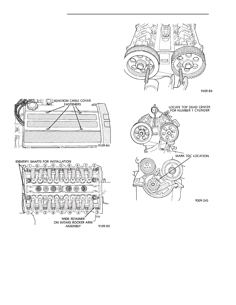
(2) Remove ignition cable cover (Fig. 7).
(3) Remove valve covers and loosen rocker arm as-
semblies about 3 turns as shown in (Fig. 8).
CAUTION: Check lash adjuster for loose or missing
retainers before continuing service procedure.
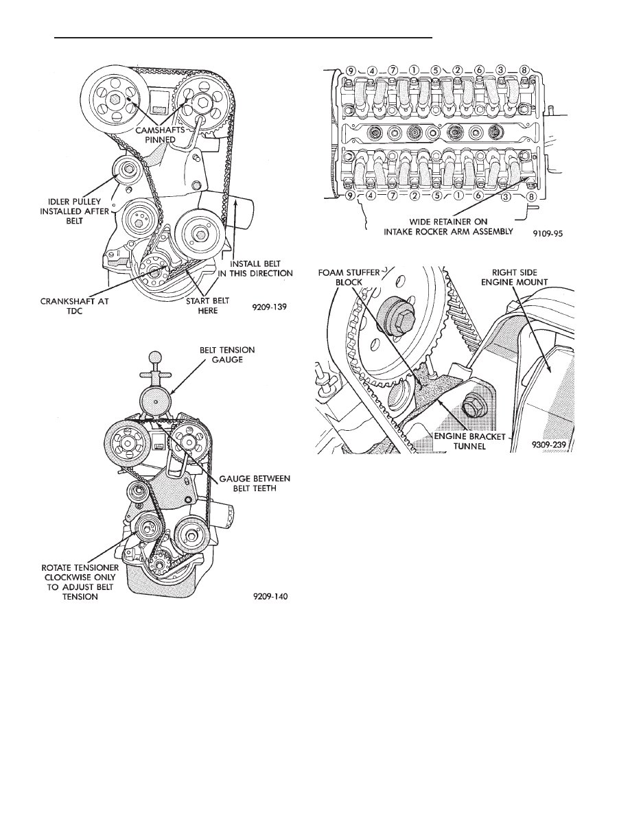
(4) Align and pin both intake and exhaust cam
sprockets with 3/32 drills or pin punches (Fig. 9). Ac-
cessory Shaft does not need to be timed.
(5) Remove spark plugs.
(6) Install a dial indicator in Number 1 spark plug
hole (Fig. 10).
(7) Rotate crankshaft till number 1 piston is at
Top Dead Center. Mark the engine block for TDC
reference.
(8) Install timing belt and idler pulley in sequence
shown in (Fig. 11).
(9) Remove dial indicator from cylinder head (Fig.
10). Remove drills or pins from camshaft sprockets
(Fig. 11).
(10) Adjust tension to 445 N (110 lbs.) New belt or
311 N (70 lbs.) Used belt . Install belt tension gauge on
timing belt (Fig. 12) adjust tensioner until specified
tension is achieved.
CAUTION: Belt tension gauge must be installed be-
tween the belt teeth to get a accurate reading.
(11) Rotate crankshaft clockwise 2 full revolutions
and check alignment of camshaft and crankshaft tim-
ing marks. Do not reverse rotate crankshaft or
attempt to rotate engine using cam or accessory
shaft attaching screw.
CAUTION: Do not allow oil or solvents to contact the
timing belt as they can deteriorate the rubber and
cause tooth skipping.
Fig. 7 Ignition Cable Cover
Fig. 8 Rocker Arm Shaft Assemblies
Fig. 9 Camshafts Pinned Into Position
Fig. 10 Dial Indicator Located in Number 1 Cylinder
9 - 34
2.2/2.5L ENGINE
Ä
(12) Recheck belt tension, adjust if necessary.
(13) Torque rocker arm shafts in sequence shown
(Fig. 13) to 12 N
Im (105 in. lbs.) then to 24 NIm (210
in. lbs.).
(14) Install valve covers, spark plugs, ignition cables
and ignition cable cover.
(15) Install air cleaner fresh air duct.
(16) Raise vehicle. Install lower timing belt cover
and accessory drive belt tensioner pulley. Refer to
procedure in this section.
(17) Lower vehicle. Install right engine mount (Fig.
5).
(18) Inspect foam stuffer block condition and posi-
tion (Fig. 14). Stuffer block should be intact and secure
within the engine bracket tunnel.
(19) Install upper timing belt cover and PCV tube.
Refer to procedure in this section.
(20) Install accessory drive belt. Refer to procedure
in this section.
SERVICING OIL SEALS
Refer to servicing oil seals in this group for proce-
dures.
To service the intake cam seal (Turbo III) the
right engine mount must be removed. Refer to
engine mount removal of this Group.
Fig. 13 Rocker Arm Shaft—Installation
Fig. 14 Foam Stuffer Block Location
Fig. 11 Camshafts and Crankshaft Timing Marks
Fig. 12 Belt Tension Gauge Location
Ä
2.2/2.5L ENGINE
9 - 35
CAMSHAFTS SERVICE
Cylinder Head must be removed from vehicle. Re-
fer to cylinder head removal for procedure.
REMOVAL
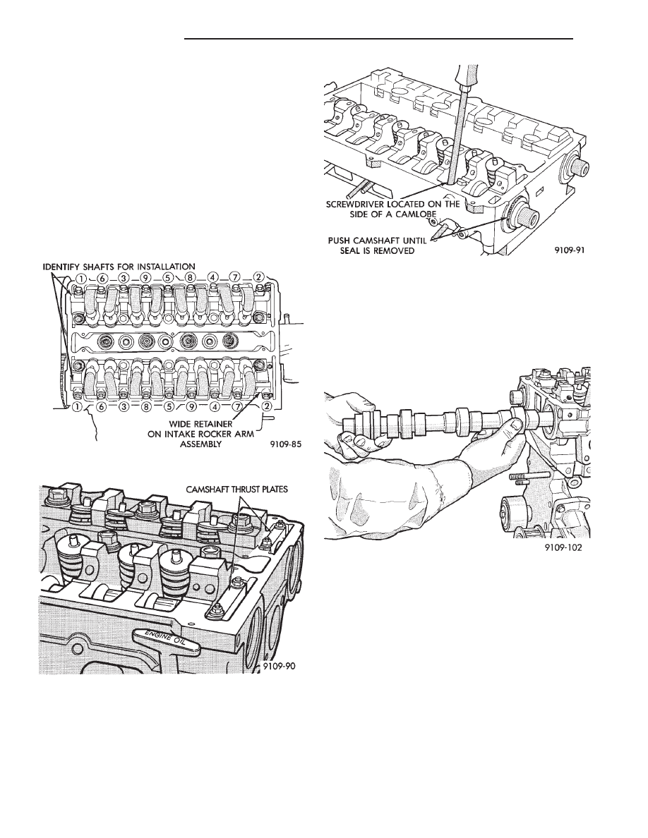
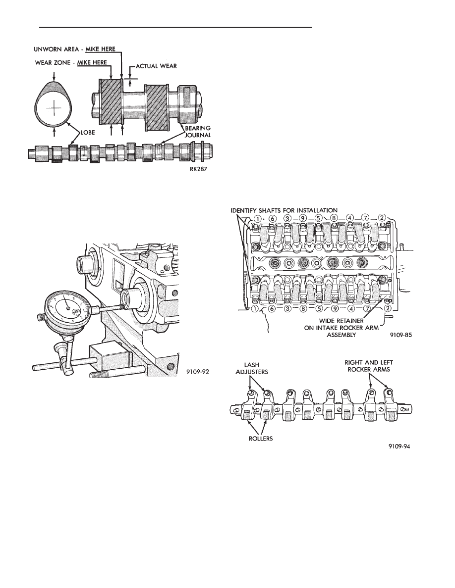
(1) Mark rocker arms shafts for reinstallation in
the same position (Fig. 1).
(2) Remove rocker arm assembly attaching bolts in
sequence (Fig. 1 ).
(3) Remove thrust plates from rear of camshafts
(Fig. 2).The intake camshaft uses a wider thrust
plate than exhaust camshaft.
CAUTION: Thrust plates are not the same thickness
and cannot be interchanged.
(4) Before camshaft can be removed from cylinder
head the cam seal must be removed first. Becareful
not to damage seal surface of the camshaft.
(5) Using a screwdriver place it against the side of
the cam lobe push the cam out of the head. The cam
seal will be pushed out by the cam (Fig. 3).
(6) Slide the camshaft out of the cylinder head. Be-
careful not scratch the bearing surfaces in the head
(Fig. 4).
CAUTION: Intake and Exhaust camshafts are not in-
terchangeable.
INSPECTION
Camshaft lobe wear should not exceed .25mm (.010
inch). To measure cam lobe wear (Fig. 4), measure
lobe diameter in two places at the largest diameter
(over the nose). Take first reading with micrometer
in unworn area at the edge of the lobe. Take second
reading in the worn area where rocker arm contacts
the lobe. Subtract second reading from the first. The
difference is the cam lobe wear.
INSTALLATION
(1) Lubricate camshaft journals with clean engine
oil. Carefully install camshaft into the head.
CAUTION: Camshafts are not interchangeable. The
intake cam has a wider thrust plate groove.
Fig. 3 Removing Camshaft Oil Seal
Fig. 1 Rocker Arm Shaft Removal Sequence
Fig. 2 Camshaft Thrust Plates
Fig. 4 Camshaft—Removal or Installation
9 - 36
2.2/2.5L ENGINE
Ä
(2) Install thrust plates and tighten retaining nuts
to 6 N
Im (55 in. lbs.).
(3) Install new camshaft oil seals flush with cylin-
der head surface.
Using seal installing special tool C-4680.
CAMSHAFT END PLAY
(1) Using a suitable tool, move camshaft as far
rearward as it will go.
(2) Zero dial indicator (Fig. 6).
(3) Move as far forward and backward as camshaft
will go.
(4) End
play
travel:
0.025-0.200mm
(.001-.008
inch).
LASH ADJUSTER (TAPPET) NOISE
A tappet-like noise may be produced from several
items. See Lash Adjuster and Tappet Noise-DIAG-
NOSIS in STANDARD SERVICE PROCEDURES,
this Group.
VALVE COMPONENTS REPLACE—CYLINDER HEAD
NOT REMOVED
ROCKER ARM AND HYDRAULIC LASH
ADJUSTER
REMOVAL
(1) Remove valve cover. Refer to procedure previ-
ously outlined in this section.
(2) Remove rocker arm shaft(s) in sequence shown
in (Fig. 6). Slide rocker off the shaft. Keep rocker
arms in order for reassembly.
CAUTION: Check lash adjusters for loose or miss-
ing retainers before continuing service procedure.
(3) Remove hydraulic lash adjuster.
Fig. 5 Measuring Camshaft Lobe Wear
Fig. 6 Checking Camshaft End Play
Fig. 7 Rocker Arm Shaft—Removal
Fig. 8 Rocker Arm and Lash Adjuster
Assembly—Right and Left
Ä
2.2/2.5L ENGINE
9 - 37
Нет комментариевНе стесняйтесь поделиться с нами вашим ценным мнением.
Текст