Chrysler Le Baron, Dodge Dynasty, Plymouth Acclaim. Manual — part 179

(5) Lift glass upward from opening at top of door.
(6) Separate glass from division channel (Fig. 21).
INSTALLATION
Reverse the preceding operation.
FRONT DOOR STATIONARY GLASS AND DIVISION
CHANNEL
REMOVAL
(1) Remove front door glass.
(2) Drill out rivets holding division channel to door
frame (Fig. 22).
(3) Separate division channel from stationary glass
and remove glass from door (Fig. 23).
(4) Lift division channel upward, out of the door.
(5) Pull the stationary glass weatherstrip from the
division channel.
INSTALLATION
Install the division channel weatherstrip on the
stationary glass. Position the glass in the door frame
and reverse the removal operation.
FRONT DOOR STATIONARY GLASS CHANNEL
WEATHERSTRIP
REMOVAL
(1) Remove stationary glass.
(2) Pull weatherstrip from door frame channel
(Fig. 24).
INSTALLATION
Loosen outside rear view mirror if necessary, and
reverse the removal operation.
Fig. 20 Division Channel Bolts
Fig. 21 Front Door Glass
Fig. 22 Pop-rivet Removal
Fig. 23 Front Door Stationary Glass
23 - 126
AP/27 CONVERTIBLE
Ä

DOOR GLASS REAR CHANNEL
REMOVAL (FIG. 25)
(1) Remove door trim panel.
(2) Raise door glass to full up position.
(3) Remove bolts holding rear channel to inner
door panel and door end frame.
(4) Separate channel from door.
INSTALLATION
Reverse the preceding operation.
FRONT DOOR BELT MOULDING AND
WEATHERSTRIP
REMOVAL (FIG. 26)
(1) Remove door glass.
(2) Remove side view mirror.
(3) Remove screws holding belt moulding to outer
door panel upper flange.
(4) Separate belt moulding and weatherstrip from
door.
INSTALLATION
Reverse the preceding operation.
FRONT DOOR STRIKER GUIDE SOCKET
REMOVAL (FIG. 27)
(1) Remove door trim panel.
(2) Remove screws holding guide socket to door
end frame.
(3) Separate guide socket from door.
INSTALLATION
Reverse the preceding operation
Fig. 24 Front Door Stationary Glass Channel
Weatherstrip
Fig. 25 Front Door Glass Rear Channel
Fig. 26 Front Door Belt Moulding and Weatherstrip
Fig. 27 Front Door Striker Guide Socket
Ä
AP/27 CONVERTIBLE
23 - 127
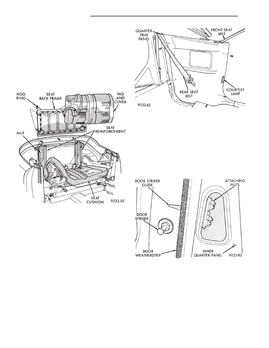
REAR SEAT BACK
REMOVAL (FIG. 28)
(1) Remove seat cushion.
(2) Raise sling well behind quarter trim panels to
gain access to seat back nuts.
(3) Reach beneath sling well and remove nuts
holding seat back to support reinforcement.
(4) Separate seat back from vehicle.
INSTALLATION
Reverse the preceding operation.
QUARTER TRIM PANEL
REMOVAL (FIG. 29)
(1) Remove bolts holding front outboard seat belt
to floor. Remove cover from belt end.
(2) Remove screws holding quarter trim to inner
quarter panel.
(3) Remove push-in fastener holding top of door
opening weatherstrip to quarter trim panel.
(4) Remove door opening sill plate as necessary to
clear quarter trim.
(5) Remove courtesy lamp and disconnect wire con-
nector.
(6) Separate trim panel from inner quarter panel
and disconnect speaker wire.
(7) Remove bolts holding rear outboard seat belt to
inner quarter panel.
(8) Push seat belt end through openings in trim
panel and remove trim panel from vehicle.
INSTALLATION
Reverse the preceding operation.
DOOR STRIKER GUIDE
REMOVAL (FIG. 30)
(1) Remove quarter trim panel as necessary to
gain access to striker guide attachments.
(2) Remove nuts holding striker guide to inner
quarter panel.
(3) Separate striker guide from lock pillar.
INSTALLATION
Reverse the preceding operation.
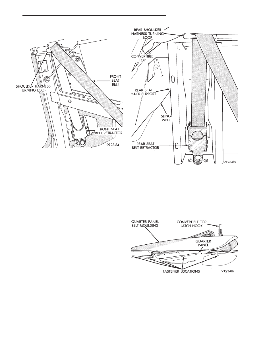
FRONT SEAT BELT RETRACTOR
REMOVAL (FIG. 31)
(1) Remove quarter trim panel as necessary to
gain access to seat belt retractor.
(2) Remove bolt holding shoulder harness turning
loop to inner quarter panel.
(3) Remove bolt holding seat belt retractor to inner
quarter panel.
(4) Separate seat belt from vehicle.
Fig. 28 Rear Seat Attaching Nuts
Fig. 29 Quarter Trim Panel
Fig. 30 Door Striker Guide
23 - 128
AP/27 CONVERTIBLE
Ä
INSTALLATION
Reverse the preceding operation.
REAR SEAT BELT RETRACTOR
REMOVAL (FIG. 32)
(1) Remove quarter trim panel as necessary to
gain access to the rear seat belt retractor.
(2) Remove snap-on cover from shoulder harness
turning loop.
(3) Remove bolt holding turning loop to rear seat
back support reinforcement.
(4) Remove bolt holding retractor to rear seat back
support reinforcement.
(5) Separate retractor from vehicle.
INSTALLATION
Reverse the preceding operation.
QUARTER PANEL BELT MOULDING
REMOVAL (FIG. 33)
(1) Lower convertible top.
(2) Remove quarter trim panel as necessary to
gain access to the belt moulding and weatherstrip at-
taching screws through the opening at the top of the
quarter panel.
(3) Remove screws holding moulding to inner quar-
ter panel in quarter glass opening.
(4) Remove nuts holding moulding to quarter
panel along top opening.
(5) Raise trunk lid. Remove nut holding moulding
to quarter panel from behind quarter panel reinforce-
ment.
(6) Separate quarter panel belt moulding from ve-
hicle.
INSTALLATION
Apply sealing putty around mounting studs on
back of moulding and reverse the removal operation.
TRUNK LID LINING
REMOVAL (FIG. 34)
(1) Raise trunk lid.
(2) Remove screws holding trunk lid lining to in-
side of trunk lid.
(3) Support trunk lid in the full up position.
(4) Disconnect trunk lid prop cylinders.
(5) Separate trunk lid lining from vehicle.
Fig. 31 Front Seat Belt Retractor
Fig. 32 Rear Seat Belt Retractor
Fig. 33 Quarter Panel Belt Moulding
Ä
AP/27 CONVERTIBLE
23 - 129
Нет комментариевНе стесняйтесь поделиться с нами вашим ценным мнением.
Текст