Chrysler Le Baron, Dodge Dynasty, Plymouth Acclaim. Manual — part 258
CLUTCH PEDAL POSITION SWITCH
The clutch pedal position switch functions as a
safety interlock device. It prevents possible engine
cranking with the clutch engaged.
The clutch pedal position switch is wired in series
between the starter relay coil and the ignition
switch.
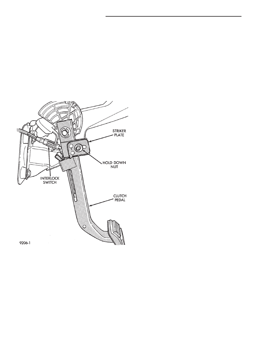
The clutch pedal position switch is mounted to a
bracket located next to the clutch pedal. The switch
is held in place by four plastic wing tabs.
The clutch pedal position switch has an adjustable
striker plate. The striker plate is located on the left
side of the clutch pedal (Fig. 3).
DIAGNOSIS
Disconnect clutch pedal position switch harness
from instrument panel wiring harness. Using a ohm
meter, check for continuity between the two termi-
nals in the connector on the switch harness. There
should be no continuity between the terminals when
the switch is in its neutral (fully extended) position.
When the switch is depressed more than 1.25 mm
(0.050) the ohm meter should show continuity.
If all ohm meter readings are correct and the
switch does not operate correctly, adjustment is re-
quired. Refer to Switch Adjustment Procedure to ad-
just switch.
REMOVAL
(1) Disconnect electrical harness to switch connec-
tor.
(2) Depress wing tabs on switch and push switch out
of mounting bracket. Then slide wires through slot in
bracket.
INSTALLATION
(1) Slide switch wires through slot in switch bracket.
(2) Line up switch tab with slot in switch bracket
and push switch into position. Do not pull on the switch
wires to seat switch into bracket, switch damage may
occur.
(3) After installation, the switch must be adjusted
and checked for proper operation. Refer to Switch
Adjustment Procedure.
ADJUSTMENT PROCEDURE
When performing switch adjustment, the floor mat
should be removed before beginning adjustment proce-
dures.
(1) Set the park brake.
(2) Disconnect clutch cable at the transaxle end of
the cable.
(3) Depress clutch pedal, loosen adjusting nut and
slide the striker plate forward to fully compress the
clutch pedal position switch plunger.
(4) Tighten adjusting nut to 12 N
Im (105 in. lbs.).
(5) Reconnect clutch cable.
The clutch pedal position switch is now ad-
justed. A final check is required to insure that the
switch is ‘‘made’’ below the clutch release point.
(1) With the park brake set and the vehicle IN
NEUTRAL turn the key to the start position. The
vehicle should not crank. If the vehicle cranks do
not continue with this test. Recheck the switch and
switch adjustment to determine the cause. If the ve-
hicle does not crank proceed to step 2.
(2) With the park brake set and the vehicle IN
GEAR turn the key to the start position.
WARNING: BEFORE PERFORMING STEP THREE BE
SURE THAT THE AREA IN FRONT OF THE VEHICLE
IS CLEAR OF OBSTRUCTIONS AND PEOPLE. VE-
HICLE MAY MOVE WHEN PERFORMING THIS TEST.
(3) Slowly depress the clutch pedal and feel for any
vehicle motion when the starter is energized. If there is
no motion the switch is properly adjusted. If motion is
felt, repeat the adjustment procedure.
Fig. 3 Clutch Pedal Position Switch and
Components
6 - 4
MANUAL TRANSAXLE CLUTCH
Ä
CLUTCH DISC REPLACEMENT
REMOVAL
(1) Remove transaxle. See Group 21, Manual Tran-
saxle, for procedure.
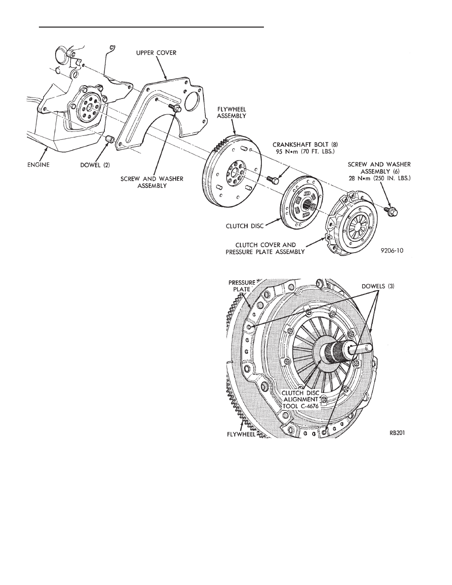
(2) Mark clutch cover and flywheel, to maintain
their same relative positions when installing clutch
assembly (Fig. 4).
(3) Insert
Clutch
Disc
Aligning
Tool
C-4676
through the clutch disc hub to prevent the clutch disc
from falling and damaging the facings (Fig. 5).
(4) Loosen clutch cover attaching bolts, one or two
turns at a time, in a crisscross pattern, to release
spring pressure evenly and avoid cover damage.
CAUTION: Do not touch the clutch disc facing with
oily or dirty hands. Oil or dirt transferred from your
hands onto the clutch disc facing may cause clutch
chatter.
(5) Remove the clutch pressure plate and cover as-
sembly and disc from flywheel. Handle carefully to
avoid contaminating the friction surfaces.
INSPECTION
(1) Inspect for oil leakage through engine rear
main bearing oil seal and transaxle input shaft seal.
If leakage is noted, it should be corrected at this
time.
(2) The friction faces of the flywheel and pressure
plate should not have excessive discoloration, burned
areas, small cracks, deep grooves, or ridges. Replace
parts as required.
CAUTION: Do not polish flywheel to a ‘‘mirror like’’
surface.
Fig. 4 Manual Transaxle Clutch
Fig. 5 Clutch Disc Aligning Tool
Ä
MANUAL TRANSAXLE CLUTCH
6 - 5
(3) Clean the flywheel face with medium sandpa-
per (80-160 grade), then wipe the surface with min-
eral spirits. If the surface is severely scored, heat
checked, or warped, replace the flywheel.
CAUTION: Do not flat-machine the flywheel face.
The surface profile is tapered.
(4) The heavy side of the flywheel is indicated by a
daub of white paint near the outside diameter. To
minimize the effects of flywheel unbalance, perform
the following installation procedure:
(a) Loose assemble the flywheel to the crank-
shaft. Use new flywheel attaching bolts which have
sealant on the threads. If new bolts are not avail-
able, apply Loctite sealant to the threads of the
original bolts. This sealant is required to prevent
engine oil leakage.
(b) Rotate the flywheel and crankshaft until the
daub of white paint (heavy side) is at the 12 o’clock
position.
(c) Torque flywheel attaching bolts to 95 N
Im(70
ft. lbs.). Use a crisscross pattern when tightening
bolts.
(5) The disc assembly should be handled without
touching the facings. Replace disc if the facings show
evidence of grease or oil soakage, or wear to within
less than .38 mm (.015 inch) of the rivet heads. The
splines on the disc hub and transaxle input shaft
should be a snug fit without signs of excessive wear.
Metallic portions of disc assembly should be dry and
clean, and not been discolored from excessive heat.
Each of the arched springs between the facings
should not be broken and all rivets should be tight.
(6) Wipe the friction surface of the pressure plate
with mineral spirits.
(7) Using a straight edge, check clutch cover (pres-
sure plate) for flatness. The clutch cover (pressure
plate) friction area should be slightly concave, with
the inner diameter 0.02 mm to 0.1 mm (.0008 in. to
.0039 in.) below the outer diameter. It should also be
free
from
discoloration,
burned
areas,
cracks,
grooves, or ridges.
(8) Using a surface plate, test cover for flatness.
All sections around attaching bolt holes should be in
contact with surface plate within .015 inch.
(9) The cover should be a snug fit on flywheel dow-
els. If the clutch assembly does not meet these re-
quirements, it should be replaced.
INSTALLATION
(1) Mount clutch assembly on flywheel,being care-
ful to properly align dowels and the alignment marks
made before removal. The flywheel side of the clutch
disc is marked for proper installation. If new clutch
or flywheel is installed, align cover balance spot as
close as possible to flywheel balance orange spot. Ap-
ply pressure to the alignment tool. Center the tip of
the tool into the crankshaft and the sliding cone into
the clutch fingers. Tighten the clutch attaching bolts
sufficiently to hold the disc in position.
(2) To avoid distortion of the clutch cover, bolts
should be tightened a few turns at a time, in a criss-
cross pattern, until they are all seated. Tighten bolts
to 28 N
Im (250 in. lbs.) following a crisscross pattern
sequence. Remove clutch disc alignment tool.
(3) Install transaxle. See group 21, Manual Tran-
saxle, for procedures.
RELEASE BEARING AND FORK
Remove the transaxle from the vehicle. See group
21 for removal and installation procedures.
REMOVAL AND INSTALLATION
(1) Remove clutch release shaft E-clip.
(2) Remove the clutch release shaft and then slide
the fork and bearing assembly off the bearing pilot.
(3) Remove the fork from the bearing thrust plate.
(4) Examine the condition of the bearing. It is pre-
lubricated and sealed and should not be im-
mersed in oil or solvent.
(5) The bearing should turn smoothly when held in
the hand under a light thrust load. A light drag
caused by the lubricant fill is normal. If the bearing
is noisy, rough, or dry, replace the complete bearing
assembly with a new bearing.
(6) The bearing has a plastic sleeve pre-lubricated
at assembly. Wipe out the old grease. Refill the
sleeve cavities and coat the inner surface with mul-
tipurpose grease. If the liner is cracked or worn, re-
place the bearing assembly.
(7) Check the condition of the spring clips. If the
clips are broken or distorted, replace the bearing as-
sembly.
(8) Before
assembling
the
fork,
lubricate
the
rounded thrust pads and the spring clip cavities with
multipurpose grease.
(9) Assemble the fork to the bearing by sliding the
thrust pads under the spring clips. Be careful to
avoid distorting the spring clips. These clips prevent
the bearing thrust plate from rotating with the bear-
ing.
(10) Slide the bearing and fork assembly onto the
input shaft bearing retainer.
(11) Position the release shaft bushings in the
housing and install the release shaft. A small
amount of bearing grease between the release shaft
bushing and the shaft is beneficial but not required.
Install the retainer clip in the shaft groove near the
large bushing.
(12) Install the release lever and retaining clip on
the outer end of the release shaft.
CLEANING PRECAUTIONS
Condensation from steam vapors tend to accumu-
late on the internal clutch mechanism when the ve-
6 - 6
MANUAL TRANSAXLE CLUTCH
Ä
hicle is steam cleaned. The facing of the disc will
absorb moisture. The force exerted by the pressure
plate will bond the facings to flywheel and/or, pres-
sure plate, if vehicle is allowed to stand for some
time before use. If this condition occurs, it will re-
quire replacement of disc assembly, flywheel, and/or
clutch assembly. After cleaning, drive the vehicle to
its normal clutch operating temperature. This will
dry off disc assembly, pressure plate, and flywheel.
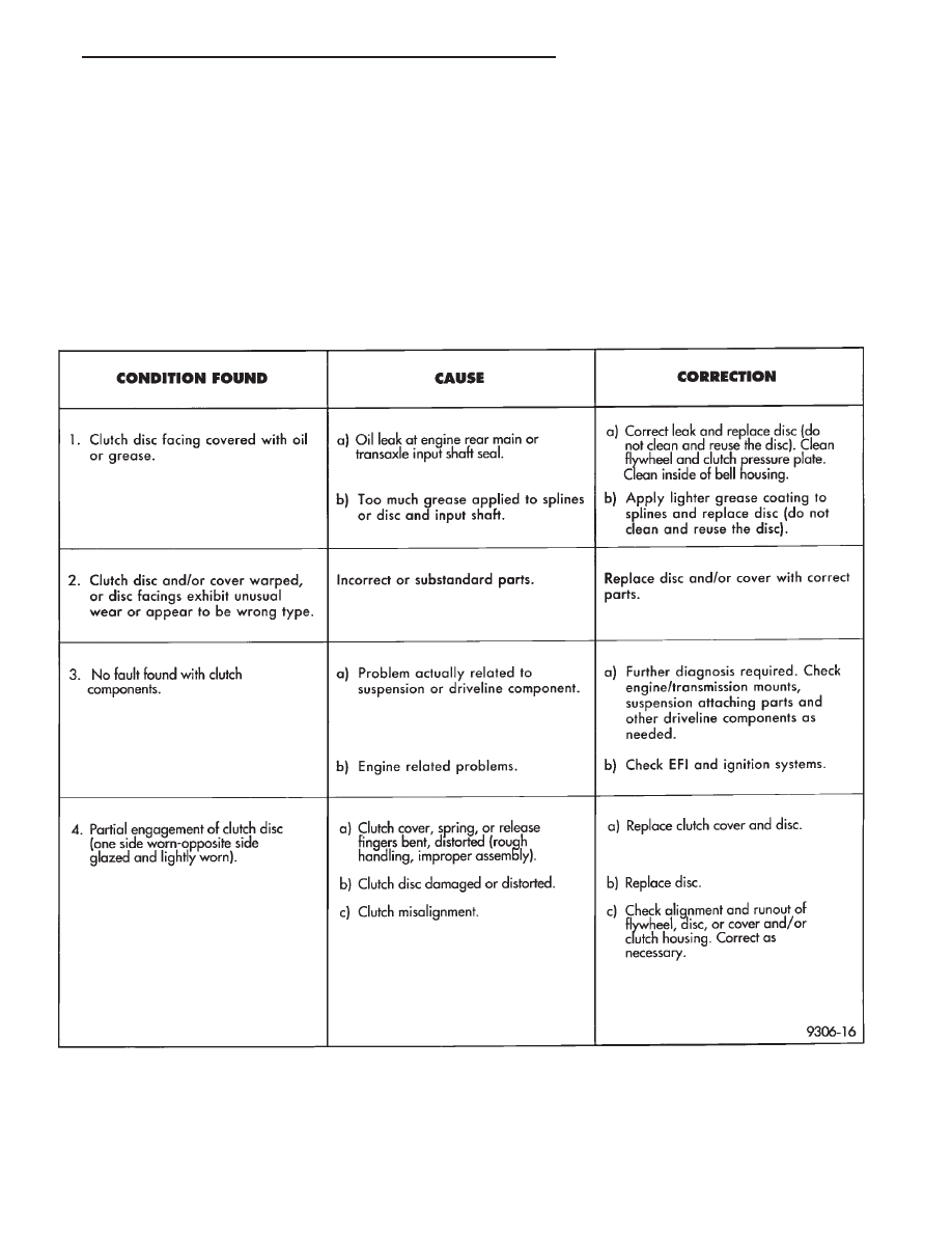
SERVICE DIAGNOSIS—CLUTCH GRAB/CHATTER
Ä
MANUAL TRANSAXLE CLUTCH
6 - 7
Нет комментариевНе стесняйтесь поделиться с нами вашим ценным мнением.
Текст