Infiniti FX35 / FX45. Manual — part 622
PRECAUTIONS
EM-5
< SERVICE INFORMATION >
[VQ35DE]
C
D
E
F
G
H
I
J
K
L
M
A
EM
N
P
O
Precaution for Assembly and Installation
INFOID:0000000001325697
• Use torque wrench to tighten bolts or nuts to specification.
• When tightening nuts and bolts, as a basic rule, equally tighten in several different steps starting with the
ones in center, then ones on inside and outside diagonally in this order. If the order of tightening is specified,
do exactly as specified.
• Replace with new gasket, packing, oil seal or O-ring.
• Dowel pins are used for several parts alignment. When replacing and reassembling parts with dowel pins,
make sure that dowel pins are installed in the original position.
• Thoroughly wash, clean, and air-blow each part. Carefully check engine oil or engine coolant passages for
any restriction and blockage.
• Avoid damaging sliding or mating surfaces. Completely remove foreign materials such as cloth lint or dust.
Before assembly, oil sliding surfaces well.
• Release air within route when refilling after draining engine coolant.
• After repairing, start the engine and increase engine speed to check engine coolant, fuel, engine oil, and
exhaust gases for leakage.
Precaution for Angle Tightening
INFOID:0000000001325698
• Use the angle wrench [SST: KV10112100 (BT8653-A)] for the final tightening of the following engine parts:
- Cylinder head bolts
- Main bearing cap bolts
- Connecting rod cap bolts
- Crankshaft pulley bolt (No the angle wrench is required as bolt flange is provided with notches for angle
tightening)
• Do not use a torque value for final tightening.
• The torque value for these parts are for a preliminary step.
• Ensure thread and seat surfaces are clean and coated with engine oil.
Precaution for Liquid Gasket
INFOID:0000000001325699
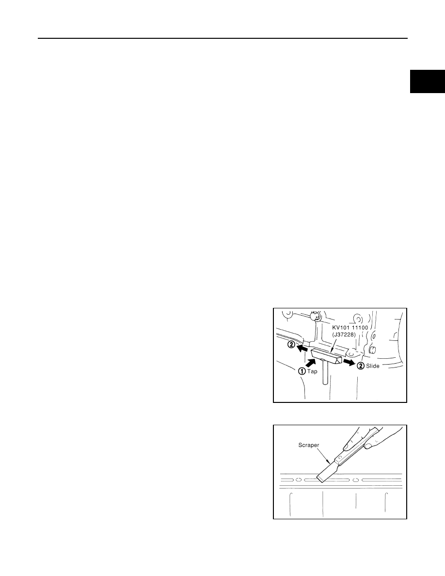
REMOVAL OF LIQUID GASKET SEALING
• After removing mounting nuts and bolts, separate the mating sur-
face using the seal cutter (SST) and remove old liquid gasket seal-
ing.
CAUTION:
Be careful not to damage the mating surfaces.
• Tap the seal cutter to insert it, and then slide it by tapping on the
side as shown in the figure.
• In areas where the seal cutter is difficult to use, use a plastic ham-
mer to lightly tap the parts, to remove it.
CAUTION:
If for some unavoidable reason tool such as a screwdriver is
used, be careful not to damage the mating surfaces.
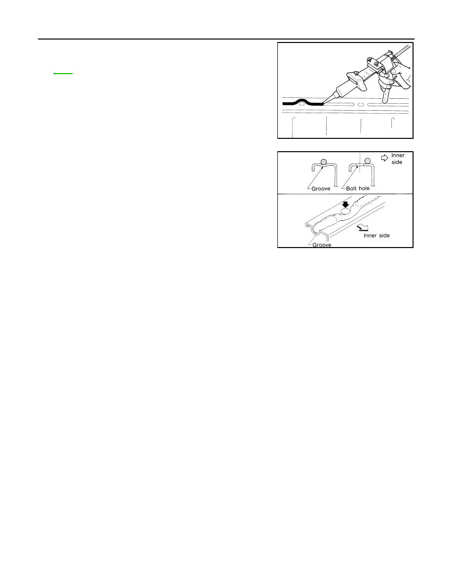
LIQUID GASKET APPLICATION PROCEDURE
1.
Using a scraper, remove old liquid gasket adhering to the gasket
application surface and the mating surface.
• Remove liquid gasket completely from the groove of the gas-
ket application surface, mounting bolts, and bolt holes.
2.
Wipe the liquid gasket application surface and the mating sur-
face with white gasoline (lighting and heating use) to remove
adhering moisture, grease and foreign materials.
PBIC0002E
PBIC0003E
EM-6
< SERVICE INFORMATION >
[VQ35DE]
PRECAUTIONS
3.
Attach liquid gasket tube to the tube presser (commercial ser-
vice tool).
Use Genuine RTV Silicone Sealant or equivalent. Refer to
.
4.
Apply liquid gasket without breaks to the specified location with
the specified dimensions.
• If there is a groove for liquid gasket application, apply liquid
gasket to the groove.
• As for bolt holes, normally apply liquid gasket inside the holes.
Occasionally, it should be applied outside the holes. Make
sure to read the text of this manual.
• Within five minutes of liquid gasket application, install the mat-
ing component.
• If liquid gasket protrudes, wipe it off immediately.
• Do not retighten mounting bolts or nuts after the installation.
• After 30 minutes or more have passed from the installation, fill
engine oil and engine coolant.
CAUTION:
If there are specific instructions in this manual, observe
them.
EMA0622D
SEM159F
PREPARATION
EM-7
< SERVICE INFORMATION >
[VQ35DE]
C
D
E
F
G
H
I
J
K
L
M
A
EM
N
P
O
PREPARATION
Special Service Tool
INFOID:0000000001325700
The actual shapes of Kent-Moore tools may differ from those of special service tools illustrated here.
Tool number
(Kent-Moore No.)
Tool name
Description
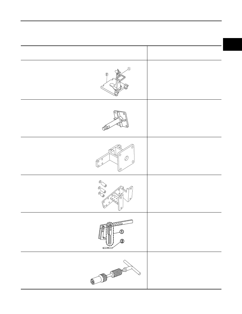
ST0501S000
(
—
)
Engine stand assembly
1. ST05011000
(
—
)
Engine stand
2. ST05012000
(
—
)
Base
Disassembling and assembling the engine
KV10106500
(
—
)
Engine stand shaft
KV10117000
(J41262)
Engine sub-attachment
KV10117000 has been replaced with
KV10117001 (KV10117000 is no longer in
production, but it is usable).
KV10117001
(
—
)
Engine sub-attachment
Installing on cylinder block
KV10116200
(J26336-A)
Valve spring compressor
1. KV10115900
(J26336-20)
Attachment
2.KV10109220
(
—
)
Adapter
Disassembling valve mechanism
Part (1) is a component of KV10116200
(J26336-A), but Part (2) is not so.
KV10107902
(J38959)
Valve oil seal puller
Replacing valve oil seal
NT042
NT028
NT373
NT372
PBIC1650E
NT011
EM-8
< SERVICE INFORMATION >
[VQ35DE]
PREPARATION
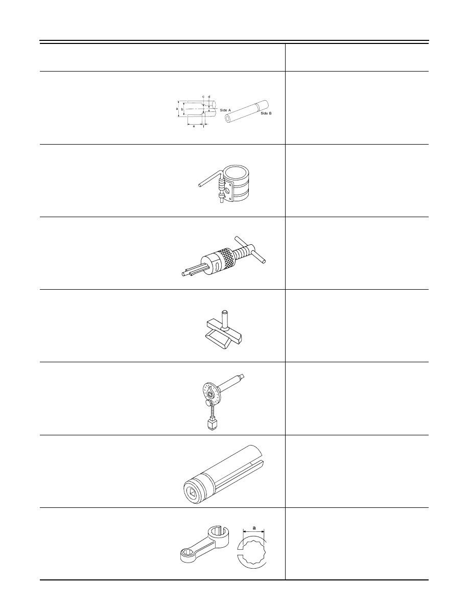
KV10115600
(J-38958)
Valve oil seal drift
Installing valve oil seal
Use side A.
a: 20 (0.79) dia. d: 8 (0.31) dia.
b: 13 (0.51) dia. e: 10.7 (0.421)
c: 10.3 (0.406) dia. f: 5 (0.20)
Unit: mm (in)
EM03470000
(J8037)
Piston ring compressor
Installing piston assembly into cylinder bore
ST16610001
(J23907)
Pilot bushing puller
Removing pilot converter
KV10111100
(J37228)
Seal cutter
Removing oil pan (lower and upper), front and
rear timing chain case, etc.
KV10112100
(BT8653-A)
Angle wrench
Tightening bolts for connecting rod bearing
cap, cylinder head, etc. in angle
KV10117100
(J3647-A)
Heated oxygen sensor wrench
Loosening or tightening heated oxygen sen-
sor 2
For 22 mm (0.87 in) width hexagon nut
KV10114400
(J38365)
Heated oxygen sensor wrench
Loosening or tightening air fuel ratio sensor 1
a: 22 mm (0.87 in)
Tool number
(Kent-Moore No.)
Tool name
Description
S-NT603
NT044
NT045
NT046
NT014
NT379
NT636
Нет комментариевНе стесняйтесь поделиться с нами вашим ценным мнением.
Текст