Infiniti FX35 / FX45. Manual — part 424
DTC P1564 ICC STEERING SWITCH
EC-457
< SERVICE INFORMATION >
[VQ35DE]
C
D
E
F
G
H
I
J
K
L
M
A
EC
N
P
O
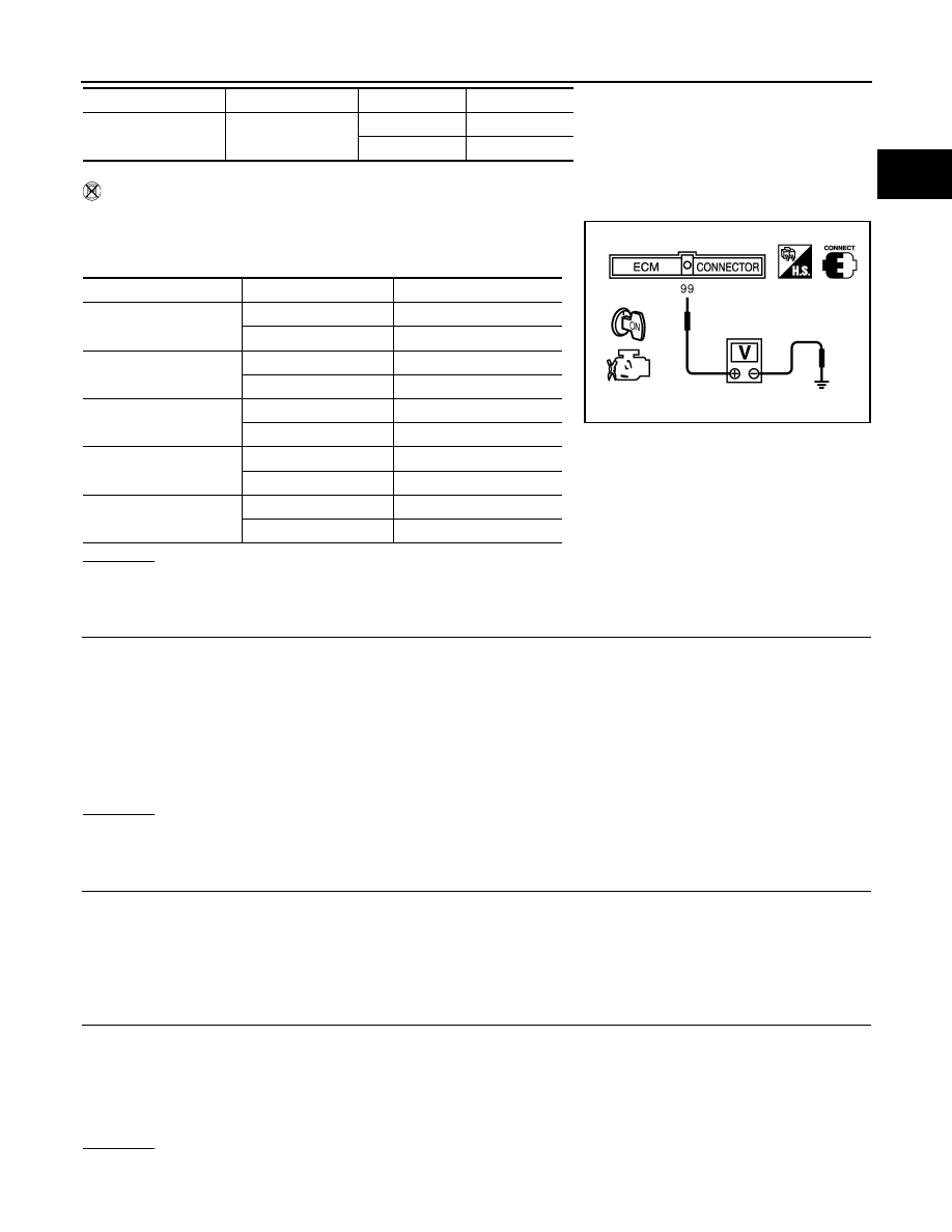
Without CONSULT-III
1.
Turn ignition switch ON.
2.
Check voltage between ECM terminal 99 and ground with press-
ing each button.
OK or NG
OK
>> GO TO 8.
NG
>> GO TO 3.
3.
CHECK ICC STEERING SWITCH GROUND CIRCUIT FOR OPEN AND SHORT
1.
Turn ignition switch OFF.
2.
Disconnect combination switch harness connector.
3.
Disconnect ECM harness connector.
4.
Check harness continuity between combination switch terminal 15 and ECM terminal 82.
Refer to Wiring Diagram.
5.
Also check harness for short to ground and short to power.
OK or NG
OK
>> GO TO 5.
NG
>> GO TO 4.
4.
DETECT MALFUNCTIONING PART
Check the following.
• Combination switch (spiral cable)
• Harness for open and short between ECM and combination switch
>> Repair open circuit or short to ground or short to power in harness or connectors.
5.
CHECK ICC STEERING SWITCH INPUT SIGNAL CIRCUIT FOR OPEN AND SHORT
1.
Check harness continuity between ECM terminal 99 and combination switch terminal 14.
Refer to Wiring Diagram.
2.
Also check harness for short to ground and short to power.
OK or NG
OK
>> GO TO 7.
DISTANCE switch
DIST SW
Pressed
ON
Released
OFF
Switch
Monitor item
Condition
Indication
Switch
Condition
Voltage [V]
MAIN switch
Pressed
Approx. 0
Released
Approx. 4.3
CANCEL switch
Pressed
Approx. 1.3
Released
Approx. 4.3
RESUME/ACCELER-
ATE switch
Pressed
Approx. 3.7
Released
Approx. 4.3
SET/COAST switch
Pressed
Approx. 3.0
Released
Approx. 4.3
DISTANCE switch
Pressed
Approx. 2.2
Released
Approx. 4.3
PBIB0311E
Continuity should exist.
Continuity should exist.
EC-458
< SERVICE INFORMATION >
[VQ35DE]
DTC P1564 ICC STEERING SWITCH
NG
>> GO TO 6.
6.
DETECT MALFUNCTIONING PART
Check the following.
• Combination switch (spiral cable)
• Harness for open and short between ECM and combination switch
>> Repair open circuit or short to ground or short to power in harness or connectors.
7.
CHECK ICC STEERING SWITCH
EC-458, "Component Inspection"
OK or NG
OK
>> GO TO 8.
NG
>> Replace ICC steering switch.
8.
CHECK INTERMITTENT INCIDENT
>> INSPECTION END
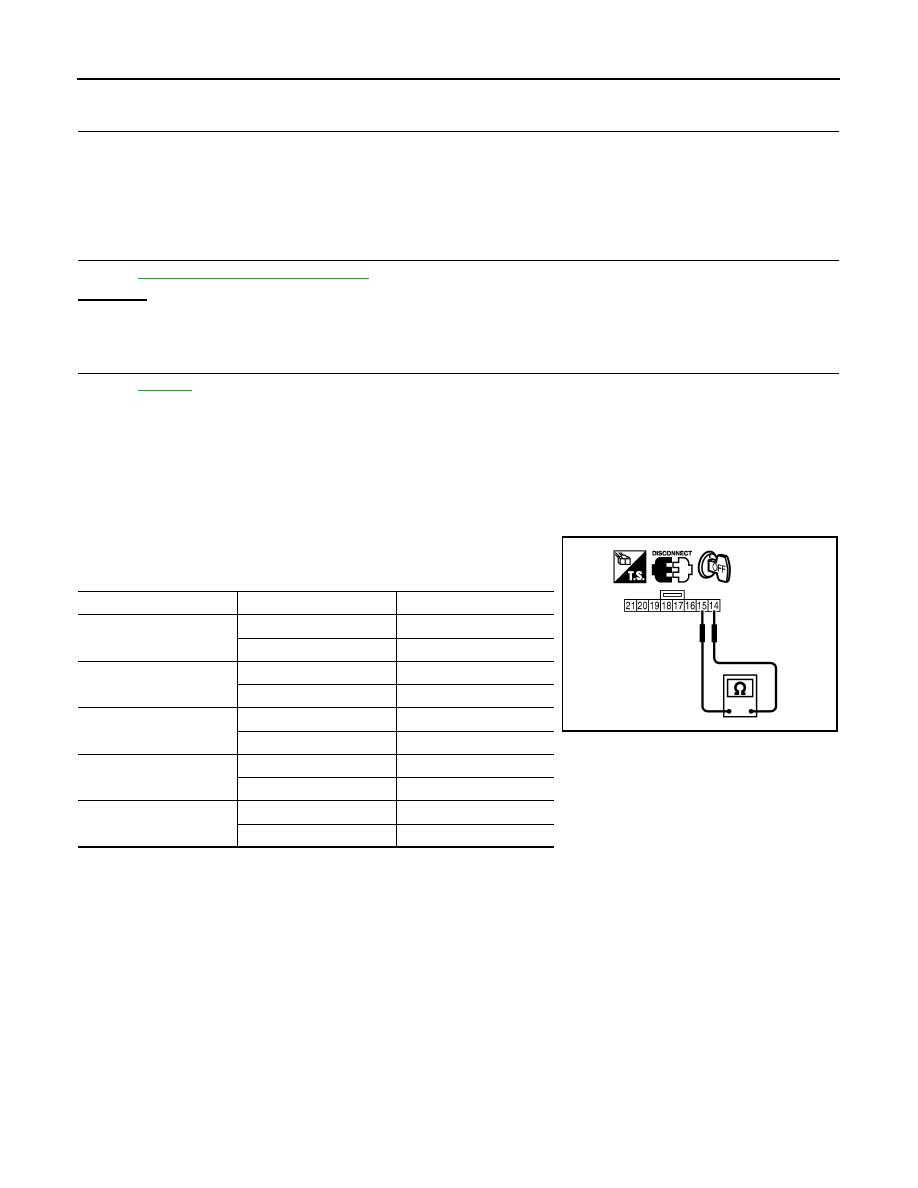
Component Inspection
INFOID:0000000001326319
ICC STEERING SWITCH
1.
Disconnect combination switch (spiral cable) harness connector M203.
2.
Check continuity between combination switch (spiral cable) ter-
minals 14 and 15 with pushing each switch.
If NG, replace ICC steering switch.
Switch
Condition
Resistance [
Ω
]
MAIN switch
Pressed
Approx. 0
Released
Approx. 5,500
CANCEL switch
Pressed
Approx. 310
Released
Approx. 5,500
RESUME/ACCELERATE
switch
Pressed
Approx. 2,600
Released
Approx. 5,500
SET/COAST switch
Pressed
Approx. 1,400
Released
Approx. 5,500
DISTANCE switch
Pressed
Approx. 740
Released
Approx. 5,500
PBIB1621E
DTC P1564 ASCD STEERING SWITCH
EC-459
< SERVICE INFORMATION >
[VQ35DE]
C
D
E
F
G
H
I
J
K
L
M
A
EC
N
P
O
DTC P1564 ASCD STEERING SWITCH
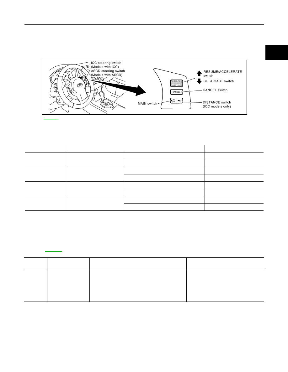
Component Description
INFOID:0000000001326320
ASCD steering switch has variant values of electrical resistance for each button. ECM reads voltage variation
of switch, and determines which button is operated.
CONSULT-III Reference Value in Data Monitor Mode
INFOID:0000000001326321
Specification data are reference values.
On Board Diagnosis Logic
INFOID:0000000001326322
• This self-diagnosis has the one trip detection logic.
• The MIL will not light up for this self-diagnosis.
NOTE:
If DTC P1564 is displayed with DTC P0605, first perform the trouble diagnosis for DTC P0605.
Refer to
.
DTC Confirmation Procedure
INFOID:0000000001326323
NOTE:
If DTC Confirmation Procedure has been previously conducted, always turn ignition switch OFF and wait at
least 10 seconds before conducting the next test.
1.
Turn ignition switch ON and wait at lest 10 seconds.
2.
Press MAIN switch for at least 10 seconds, then release it and wait at least 10 seconds.
3.
Press RESUME/ACCELERATE switch for at least 10 seconds, then release it and wait at least 10 sec-
onds.
PBIB3255E
MONITOR ITEM
CONDITION
SPECIFICATION
MAIN SW
• Ignition switch: ON
MAIN switch: Pressed
ON
MAIN switch: Released
OFF
CANCEL SW
• Ignition switch: ON
CANCEL switch: Pressed
ON
CANCEL switch: Released
OFF
RESUME/ACC SW
• Ignition switch: ON
RESUME/ACCELERATE switch: Pressed
ON
RESUME/ACCELERATE switch: Released
OFF
SET SW
• Ignition switch: ON
SET/COAST switch: Pressed
ON
SET/COAST switch: Released
OFF
DTC No.
Trouble Diagnosis
Name
DTC Detecting Condition
Possible Cause
P1564
1564
ASCD steering switch
• An excessively high voltage signal from the ASCD
steering switch is sent to ECM.
• ECM detects that input signal from the ASCD steer-
ing switch is out of the specified range.
• ECM detects that the ASCD steering switch is stuck
ON.
• Harness or connectors
(ASCD steering switch circuit is open or
shorted.)
• ASCD steering switch
• ECM
EC-460
< SERVICE INFORMATION >
[VQ35DE]
DTC P1564 ASCD STEERING SWITCH
4.
Press SET/COAST switch for at least 10 seconds, then release it and wait at least 10 seconds.
5.
Press CANCEL switch for at least 10 seconds, then release it and wait at least 10 seconds.
6.
Check DTC.
7.
If DTC is detected, go to
.
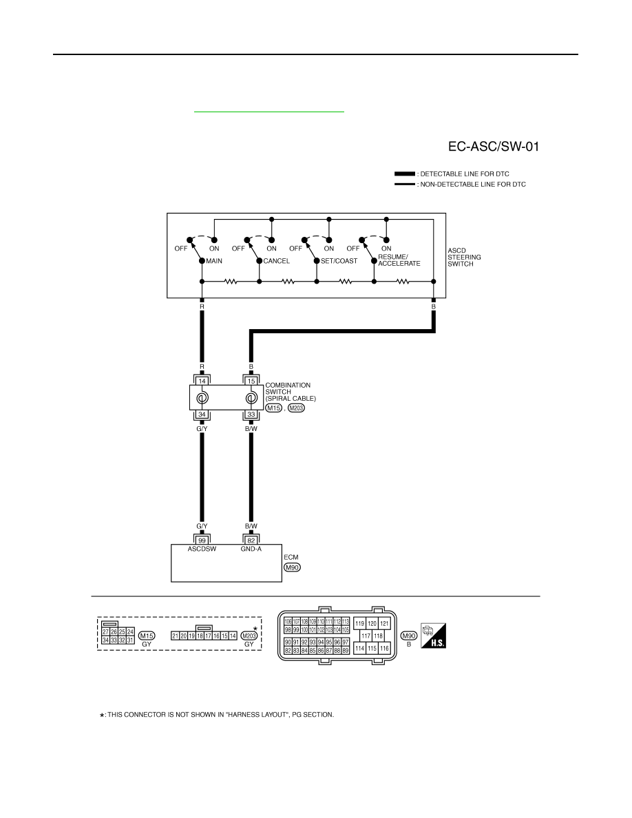
Wiring Diagram
INFOID:0000000001326324
TBWM0733E
Нет комментариевНе стесняйтесь поделиться с нами вашим ценным мнением.
Текст