Infiniti FX35 / FX45. Manual — part 670

ROCKER COVER
EM-197
< SERVICE INFORMATION >
[VK45DE]
C
D
E
F
G
H
I
J
K
L
M
A
EM
N
P
O
7.
Remove grommets from right and left cowl top panel.
• Remove right side grommet as follows:
- Remove battery. Refer to
- Remove battery tray.
- Remove grommet.
8.
Loosen mounting bolts in reverse order as shown in the figure.
CAUTION:
Do not hold oil filler neck (right bank) not to damage it.
NOTE:
Loosen No. 10 bolt of the right bank and No. 10 and 12 bolts of
the left bank from cowl top panel hole with using tool.
9.
Remove rocker cover gaskets from rocker covers.
10. Use scraper to remove all traces of liquid gasket from cylinder head and camshaft bracket (No. 1 and 6).
CAUTION:
Do not scratch or damage the mating surface when cleaning off oil liquid gasket.
INSTALLATION
PBIC2339E
PBIC0027E

EM-198
< SERVICE INFORMATION >
[VK45DE]
ROCKER COVER
1.
Apply liquid gasket with tube presser (commercial service tool)
to joint among rocker cover, cylinder head and camshaft bracket
(No. 1 and 6) as follows:
Use Genuine RTV Silicone Sealant or equivalent. Refer to
GI-44, "Recommended Chemical Product and Sealant"
NOTE:
The figure shows an example of left bank side [zoomed in shows
camshaft bracket (No. 1)]. Apply only to camshaft bracket (No.
1) for right bank side.
a.
Refer to the figure “a” to apply liquid gasket to joint part of cam-
shaft bracket (both No. 1 and 6) and cylinder head.
b.
Refer to the figure “b” to apply liquid gasket to the figure “a”
squarely.
2.
Install new rocker cover gaskets to rocker covers.
3.
Install rocker cover.
• Check if rocker cover gasket is not dropped from installation groove of rocker cover.
4.
Tighten mounting bolts in two steps separately in numerical
order as shown in the figure.
CAUTION:
Do not hold oil filler neck (right bank) not to damage it.
NOTE:
Tighten No. 10 bolt of the right bank and No. 10 and 12 bolts of
the left bank from cowl top panel hole with using tool.
5.
Install oil filler cap and oil catcher to rocker cover (right bank), if removed.
6.
Install new O-rings and PCV valves to rocker covers (right and left bank), if removed.
7.
Install in the reverse order of removal.
PBIC2444E
1st step
: 2.0 N·m (0.2 kg-m, 18 in-lb)
2nd step
: 8.3 N·m (0.85 kg-m, 73 in-lb)
PBIC0027E
TIMING CHAIN
EM-199
< SERVICE INFORMATION >
[VK45DE]
C
D
E
F
G
H
I
J
K
L
M
A
EM
N
P
O
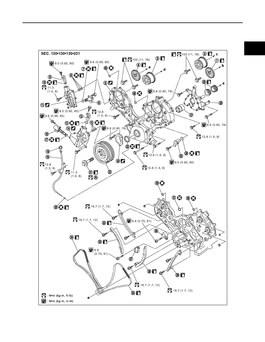
TIMING CHAIN
Component
INFOID:0000000001325788
1.
Camshaft sprocket (EXH)
2.
Camshaft sprocket (INT)
3.
Camshaft sprocket (INT)
4.
Camshaft sprocket (EXH)
5.
Front cover
6.
Intake valve timing control solenoid
valve (right bank)
PBIC4570E
EM-200
< SERVICE INFORMATION >
[VK45DE]
TIMING CHAIN
• Refer to
for symbols in the figure.
Removal and Installation
INFOID:0000000001325789
REMOVAL
1.
Remove engine assembly from vehicle. Refer to
2.
Remove the following components and related parts:
• Drive belt auto tensioner and idler pulley: Refer to
EM-172, "Drive Belt Auto Tensioner and Idler Pulley"
.
• Thermostat housing and hoses: Refer to
.
• Ignition coil: Refer to
.
• Rocker cover: Refer to
.
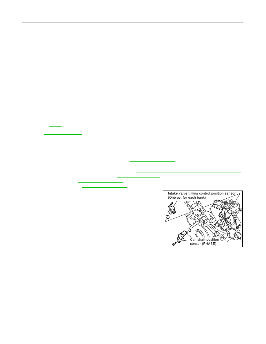
3.
If necessary, remove intake valve timing control position sensor
(right and left bank) and camshaft position sensor (PHASE) from
intake valve timing control cover and front cover.
CAUTION:
• Handle carefully to avoid dropping and shocks.
• Do not disassemble.
4.
If necessary, remove intake valve timing control solenoid valve from intake valve timing control cover.
CAUTION:
• Handle components and parts carefully to avoid dropping and shocks.
• Do not disassemble.
• Do not allow metal powder to adhere to magnetic part at sensor tip.
• Do not place sensors in a location where they are exposed to magnetism.
7.
O-ring
8.
Seal ring
9.
Intake valve timing control position
sensor (right bank)
10.
O-ring
11.
Intake valve timing control cover
(right bank)
12.
Intake valve timing control position
sensor (left bank)
13.
O-ring
14.
Intake valve timing control cover (left
bank)
15.
Seal ring
16.
Intake valve timing control solenoid-
valve (left bank)
17.
O-ring
18.
Oil level gauge
19.
Oil level gauge guide
20.
O-ring
21.
Crankshaft pulley bolt
22.
Crankshaft pulley
23.
Front oil seal
24.
Chain tensioner cover
25.
Camshaft position sensor (PHASE)
26.
O-ring
27.
Oil pump drive spacer
28.
Oil pump assembly
29.
Crankshaft sprocket
30.
O-ring
31.
O-ring
32.
Timing chain tension guide
(right bank)
33.
Timing chain slack guide
(right bank)
34.
Timing chain (right bank)
35.
Timing chain (left bank)
36.
Chain tensioner (left bank)
37.
Chain tensioner (right bank)
38.
Timing chain slack guide
(left bank)
39.
Timing chain tension guide
(left bank)
40.
O-ring
A.
Refer to
PBIC0050E
Нет комментариевНе стесняйтесь поделиться с нами вашим ценным мнением.
Текст