Infiniti FX35 / FX45. Manual — part 693
FAX-8
< SERVICE INFORMATION >
[AWD]
PREPARATION
PREPARATION
Special Service Tool
INFOID:0000000001327510
The actual shapes of Kent-Moore tools may differ from those of special service tools illustrated here.
Tool number
(Kent-Moore No.)
Tool name
Description
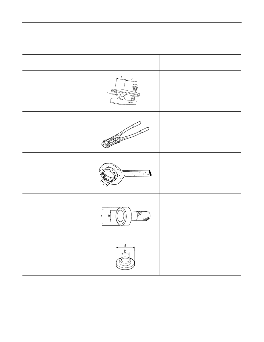
HT72520000
(J
−
25730-A)
Ball joint remover
a: 33 mm (1.30 in)
b: 50 mm (1.97 in)
r: 11.5 mm (0.453 in)
• Removing steering outer socket
• Removing transverse link
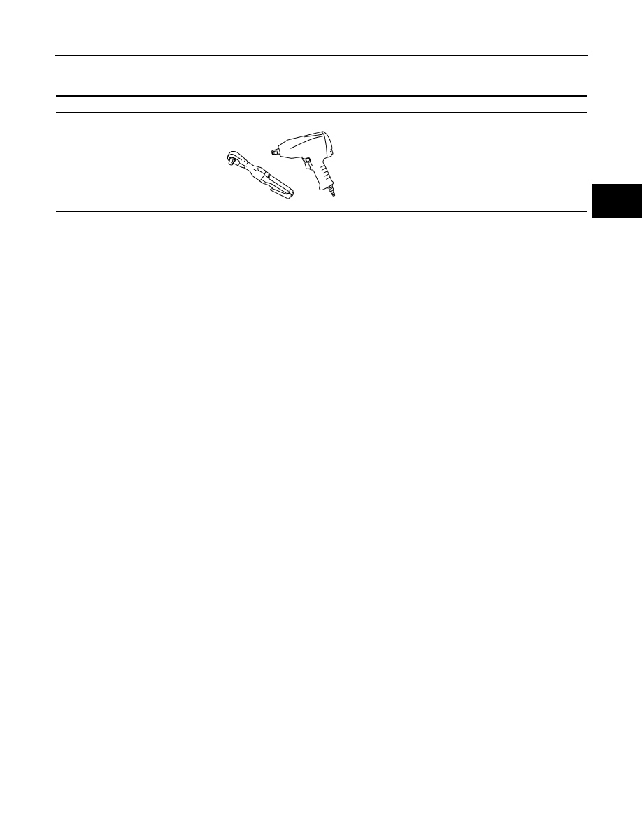
KV40107300
(
–
)
Boot band crimping tool
Installing boot band
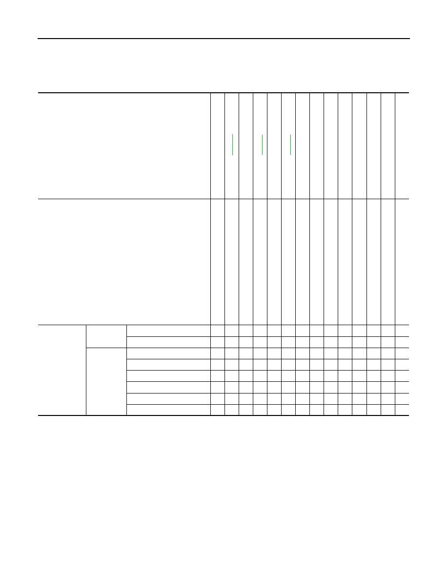
KV38107900
(
–
)
Protector
a: 32 mm (1.26 in) dia.
Installing drive shaft
KV38100500
(
–
)
Drift
a: 80 mm (3.15 in) dia.
b: 60 mm (2.36 in) dia.
Installing drive shaft plug
KV38102200
(
–
)
Drift
a: 90 mm (3.54 in) dia.
b: 31 mm (1.22 in) dia.
Installing drive shaft plug
NT546
ZZA1229D
ZZA0835D
ZZA0701D
ZZA0920D
PREPARATION
FAX-9
< SERVICE INFORMATION >
[AWD]
C
E
F
G
H
I
J
K
L
M
A
B
FAX
N
O
P
Commercial Service Tool
INFOID:0000000001327511
Tool name
Description
Power tool
Loosening bolt and nuts
PBIC0190E
FAX-10
< SERVICE INFORMATION >
[AWD]
NOISE, VIBRATION AND HARSHNESS (NVH) TROUBLESHOOTING
NOISE, VIBRATION AND HARSHNESS (NVH) TROUBLESHOOTING
NVH Troubleshooting Chart
INFOID:0000000001327512
Use chart below to help you find the cause of the symptom. If necessary, repair or replace these parts.
×
: Applicable
Reference page
—
—
—
NVH in FFD section
NV
H in
F
A
X
an
d
FSU s
e
c
tio
n
Re
fe
r to
FRONT AXL
E i
n
t
h
is cha
rt.
NVH in WT
section
NVH in WT
section
Ref
e
r t
o
DRIV
E SHAFT
in
th
is ch
art
.
NVH in BR
section
NVH in PS
section
Possible cause and SUSPECTED PARTS
Ex
ce
ss
iv
e joi
nt
an
gl
e
Jo
in
t sl
id
in
g
re
si
st
a
n
c
e
Im
ba
la
nc
e
Imp
rop
er i
ns
ta
lla
ti
o
n,
lo
os
en
es
s
Part
s interf
erence
Whe
e
l be
ari
n
g
da
ma
ge
FRONT DI
FFERENTI
A
L
FRONT A
X
LE
AND FRONT SUSP
ENSION
FRONT A
XLE
TI
RE
ROAD WHEE
L
DRIVE SHAFT
BRAKE
STE
E
RING
Symptom
DRIVE
SHAFT
Noise
×
×
×
×
×
×
×
×
×
×
Shake
×
×
×
×
×
×
×
×
×
FRONT
AXLE
Noise
×
×
×
×
×
×
×
×
×
×
Shake
×
×
×
×
×
×
×
×
×
Vibration
×
×
×
×
×
×
×
Shimmy
×
×
×
×
×
×
×
Judder
×
×
×
×
×
×
Poor quality ride or handling
×
×
×
×
×
FRONT WHEEL HUB AND KNUCKLE
FAX-11
< SERVICE INFORMATION >
[AWD]
C
E
F
G
H
I
J
K
L
M
A
B
FAX
N
O
P
FRONT WHEEL HUB AND KNUCKLE
On-Vehicle Inspection
INFOID:0000000001327513
Make sure the mounting conditions (looseness, back lash) of each component and component status (wear,
damage) are normal.
WHEEL BEARING INSPECTION
• Move wheel hub in the axial direction by hand. Check that there is no looseness of front wheel bearing.
• Rotate wheel hub and make sure there is no unusual noise or other irregular conditions. If there are any
irregular conditions, replace wheel hub and bearing assembly.
Removal and Installation
INFOID:0000000001327514
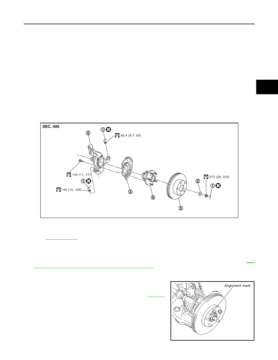
COMPONENTS
REMOVAL
1.
Remove tires from vehicle with power tool.
2.
Remove brake caliper with power tool. Hang it in a place where it will not interfere with work. Refer to
19, "Removal and Installation of Brake Caliper Assembly"
.
NOTE:
Avoid depressing brake pedal while brake caliper is removed.
3.
Put alignment marks on disc rotor and wheel hub and bearing
assembly, then remove disc rotor.
4.
Remove wheel sensor from steering knuckle. Refer to
CAUTION:
Do not pull on wheel sensor harness.
Axial end play
: 0.05 mm (0.002 in) or less
1.
Cotter pin
2.
Washer
3.
Disc rotor
4.
Wheel hub and bearing assembly
5.
Splash guard
6.
Steering knuckle
Refer to
, for the symbols in the figure.
PDIA1217E
SDIA1480E
Нет комментариевНе стесняйтесь поделиться с нами вашим ценным мнением.
Текст