Infiniti FX35 / FX45. Manual — part 246
BR-1
BRAKES
C
D
E
G
H
I
J
K
L
M
SECTION
BR
A
B
BR
N
O
P
CONTENTS
BRAKE SYSTEM
SERVICE INFORMATION . . . . . . .
PRECAUTIONS . . . . . . . . . . . . ...
Precaution for Procedure without Cowl Top Cover
. ..
Precaution for Brake System . . . . . . . . ....
PREPARATION . . . . . . . . . . . . ...
Commercial Service Tool . . . . . . . . . . ..
NOISE, VIBRATION AND HARSHNESS
(NVH) TROUBLESHOOTING . . . . . . . .
NVH Troubleshooting Chart . . . . . . . . . ..
BRAKE PEDAL . . . . . . . . . . . . ...
Inspection and Adjustment . . . . . . . . . ....
Component . . . . . . . . . . . . . . . ....
Removal and Installation . . . . . . . . . . ...
BRAKE FLUID . . . . . . . . . . . . . .
On-Board Inspection . . . . . . . . . . . .....
Drain and Refill . . . . . . . . . . . . . . ..
Bleeding Brake System . . . . . . . . . . .....
BRAKE TUBE AND HOSE . . . . . . . .
Hydraulic Circuit . . . . . . . . . . . . . ..
Removal and Installation of Front Brake Tube and
Brake Hose . . . . . . . . . . . . . . . .
Removal and Installation of Rear Brake Piping
and Brake Hose . . . . . . . . . . . . . ..
Inspection After Installation . . . . . . . . . .
BRAKE MASTER CYLINDER . . . . . . .
On-Board Inspection . . . . . . . . . . . ...
Component . . . . . . . . . . . . . . . ..
Removal and Installation . . . . . . . . . . .
Disassembly and Assembly . . . . . . . . .
BRAKE BOOSTER . . . . . . . . . . ...
On-Vehicle Service . . . . . . . . . . . . ..
Component . . . . . . . . . . . . . . . ..
Removal and Installation . . . . . . . . . . .
VACUUM LINES . . . . . . . . . . . ...
Component . . . . . . . . . . . . . . . ..
Removal and Installation . . . . . . . . . . .
Inspection . . . . . . . . . . . . . . . .
FRONT DISC BRAKE . . . . . . . . . ...
On-Vehicle Inspection . . . . . . . . . . . .
Component . . . . . . . . . . . . . . . ..
Removal and Installation of Brake Pad . . . . ...
Removal and Installation of Brake Caliper Assem-
bly . . . . . . . . . . . . . . . . . . .
Disassembly and Assembly of Brake Caliper As-
sembly . . . . . . . . . . . . . . . . . .
Brake Burnishing Procedure . . . . . . . . .
REAR DISC BRAKE . . . . . . . . . . .
On-Vehicle Inspection . . . . . . . . . . . .
Component . . . . . . . . . . . . . . . ..
Removal and Installation of Brake Pad . . . . ...
Removal and Installation of Brake Caliper Assem-
bly . . . . . . . . . . . . . . . . . . .
Disassembly and Assembly of Brake Caliper As-
sembly . . . . . . . . . . . . . . . . . .
Brake Burnishing Procedure . . . . . . . . .
SERVICE DATA AND SPECIFICATIONS
(SDS) . . . . . . . . . . . . . . . . .
General Specification . . . . . . . . . . . ..
Brake Pedal . . . . . . . . . . . . . . . .
Brake Booster . . . . . . . . . . . . . . ..
Check Valve . . . . . . . . . . . . . . .
Front Disc Brake . . . . . . . . . . . . . ..

BR-2
< SERVICE INFORMATION >
PRECAUTIONS
SERVICE INFORMATION
PRECAUTIONS
Precaution for Supplemental Restraint System (SRS) "AIR BAG" and "SEAT BELT
PRE-TENSIONER"
INFOID:0000000001612918
The Supplemental Restraint System such as “AIR BAG” and “SEAT BELT PRE-TENSIONER”, used along
with a front seat belt, helps to reduce the risk or severity of injury to the driver and front passenger for certain
types of collision. This system includes seat belt switch inputs and dual stage front air bag modules. The SRS
system uses the seat belt switches to determine the front air bag deployment, and may only deploy one front
air bag, depending on the severity of a collision and whether the front occupants are belted or unbelted.
Information necessary to service the system safely is included in the “SUPPLEMENTAL RESTRAINT SYS-
TEM” and “SEAT BELTS” of this Service Manual.
WARNING:
• To avoid rendering the SRS inoperative, which could increase the risk of personal injury or death in
the event of a collision which would result in air bag inflation, all maintenance must be performed by
an authorized NISSAN/INFINITI dealer.
• Improper maintenance, including incorrect removal and installation of the SRS, can lead to personal
injury caused by unintentional activation of the system. For removal of Spiral Cable and Air Bag
Module, see the “SUPPLEMENTAL RESTRAINT SYSTEM”.
• Do not use electrical test equipment on any circuit related to the SRS unless instructed to in this
Service Manual. SRS wiring harnesses can be identified by yellow and/or orange harnesses or har-
ness connectors.
Precaution for Procedure without Cowl Top Cover
INFOID:0000000001612920
When performing the procedure after removing cowl top cover, cover
the lower end of windshield with urethane, etc.
Precaution for Brake System
INFOID:0000000001327604
• Clean dust on front brake and rear brake with a vacuum dust collector. Do not blow with compressed air.
• Recommended fluid is brake fluid “DOT 3”.
.
• Do not reuse drained brake fluid.
• Be careful not to splash brake fluid on painted areas.
• To clean or wash all parts of master cylinder, disc brake caliper and wheel cylinder, use new brake fluid.
• Do not use mineral oils such as gasoline or kerosene. They will ruin rubber parts of the hydraulic system.
• Use a flare nut crowfoot and torque wrench when installing brake
tube.
• When installing brake piping, be sure to check torque.
• Before working, turn ignition switch OFF and disconnect connec-
tors for ABS actuator and electric unit (control unit) or battery neg-
ative terminal.
• Burnish the brake contact surfaces after refinishing or replacing
drums or rotors, after replacing pads or linings, or if a soft pedal
occurs at very low mileage.
Refer to
BR-23, "Brake Burnishing Procedure"
(Front disc brake),
BR-29, "Brake Burnishing Procedure"
WARNING:
• Clean brake pads and shoes with a waste cloth, then clean with a dust collector.
PIIB3706J
SBR686C

PREPARATION
BR-3
< SERVICE INFORMATION >
C
D
E
G
H
I
J
K
L
M
A
B
BR
N
O
P
PREPARATION
Commercial Service Tool
INFOID:0000000001327605
Tool name
Description
1.Flare nut crowfoot
a: 10 mm (0.39 in) / 12 mm (0.47 in)
2.Torque wrench
Installing each brake piping
Pin punch
Tip diameter: 4 mm (0.16 in) dia.
Removing and installing reservoir tank
pin
Power tool
Loosening bolts and nuts
S-NT360
ZZA0515D
PBIC0190E
BR-4
< SERVICE INFORMATION >
NOISE, VIBRATION AND HARSHNESS (NVH) TROUBLESHOOTING
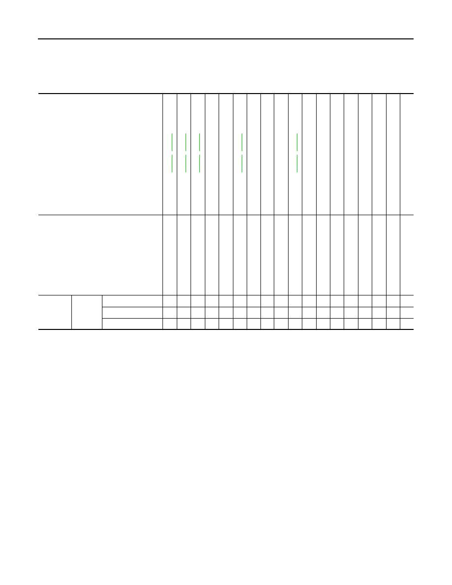
NOISE, VIBRATION AND HARSHNESS (NVH) TROUBLESHOOTING
NVH Troubleshooting Chart
INFOID:0000000001327606
Use the chart below to help you find the cause of the symptom. If necessary, repair or replace these parts.
×
: Applicable
Reference page
,
,
,
—
—
,
—
—
—
,
—
NVH in P
R
section
NVH in FFD an
d RFD section
NVH in F
AX,
RAX and FSU,
RSU section
NVH in WT section
NVH in WT section
NVH i
n
F
AX and RAX
secti
o
n
NVH in P
S
section
Possible cause and
SUSPECTED PARTS
P
a
d
s
-
da
ma
ge
d
P
a
d
s
-
un
ev
en
wea
r
S
him
s
da
ma
ge
d
Ro
to
r im
ba
lan
c
e
Ro
to
r da
ma
ge
Rotor runout
Ro
to
r de
form
a
tio
n
Ro
to
r de
fle
c
ti
on
Rotor rust
Ro
to
r th
ickne
s
s vari
ati
o
n
Dru
m
ou
t o
f ro
und
PR
O
P
EL
LE
R
S
H
A
F
T
DIFFERENTIAL
A
XLE AND
SUSPENSI
ON
TI
RE
ROAD W
H
EEL
DRI
VE SHAFT
S
T
EERING
Symptom
BRAKE
Noise
×
×
×
×
×
×
×
×
×
×
Shake
×
×
×
×
×
×
×
Shimmy, Judder
×
×
×
×
×
×
×
×
×
×
×
Нет комментариевНе стесняйтесь поделиться с нами вашим ценным мнением.
Текст