Infiniti FX35 / FX45. Manual — part 605

REFRIGERANT PRESSURE SENSOR
EC-1181
< SERVICE INFORMATION >
[VK45DE]
C
D
E
F
G
H
I
J
K
L
M
A
EC
N
P
O
OK
>> GO TO 9.
NG
>> GO TO 8.
8.
DETECT MALFUNCTIONING PART
Check the following.
• Harness connectors E17, F47
• Harness for open or short between ECM and refrigerant pressure sensor
>> Repair open circuit or short to ground or short to power in harness or connectors.
9.
CHECK INTERMITTENT INCIDENT
OK or NG
OK
>> Replace refrigerant pressure sensor.
NG
>> Repair or replace.
Removal and Installation
INFOID:0000000001327076
REFRIGERANT PRESSURE SENSOR
ATC-137, "Removal and Installation of Refrigerant Pressure Sensor"
.

EC-1182
< SERVICE INFORMATION >
[VK45DE]
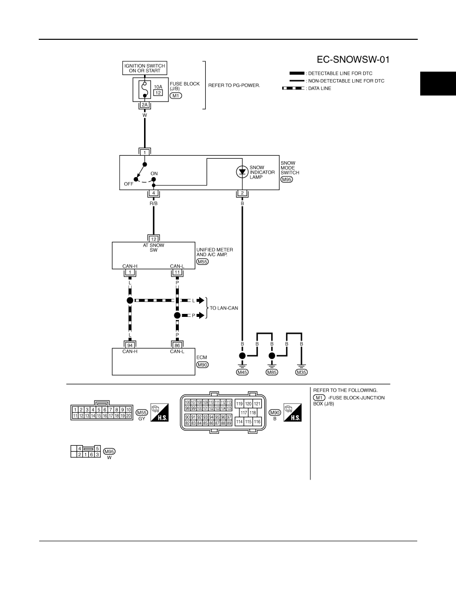
SNOW MODE SWITCH
SNOW MODE SWITCH
Description
INFOID:0000000001327077
The snow mode switch signal is sent to the “unified meter and A/C amp.” from the snow mode switch. The
“unified meter and A/C amp.” then sends the signal to the ECM by CAN communication line.
The snow mode is used for driving or starting the vehicle on snowy roads or slippery areas. If the snow mode
is activated, the vehicle speed will not be accelerated immediately than your original pedal in due to avoid the
vehicle slip. In other words, ECM controls the rapid engine torque change by controlling the electric throttle
control actuator operating speed.
CONSULT-III Reference Value in Data Monitor Mode
INFOID:0000000001327078
MONITOR ITEM
CONDITION
SPECIFICATION
SNOW MODE SW
• Ignition switch: ON
Snow mode switch: ON
ON
Snow mode switch: OFF
OFF
SNOW MODE SWITCH
EC-1183
< SERVICE INFORMATION >
[VK45DE]
C
D
E
F
G
H
I
J
K
L
M
A
EC
N
P
O
Wiring Diagram
INFOID:0000000001327079
Diagnosis Procedure
INFOID:0000000001327080
1.
CHECK SNOW MODE SWITICH OVERALL FUNCTION-I
1.
Turn ignition switch ON.
2.
Select “SNOW MODE SW” in “DATA MONITOR” mode with CONSULT-III.
3.
Check “SNOW MODE SW” indication under the following conditions.
TBWM1369E
EC-1184
< SERVICE INFORMATION >
[VK45DE]
SNOW MODE SWITCH
OK or NG
OK
>> GO TO 2.
NG
>> GO TO 3.
2.
CHECK SNOW MODE SWITICH OVERALL FUNCTION-II
1.
Turn ignition switch ON.
2.
Start engine.
3.
Check the snow indicator lamp under the following condition.
OK or NG
OK
>> INSPECTION END
NG
>> GO TO 7.
3.
CHECK DTC WITH “UNIFIED METER AND A/C AMP.”
DI-27, "CONSULT-III Function (METER/M&A)"
OK or NG
OK
>> GO TO 4.
NG
>> Go to
.
4.
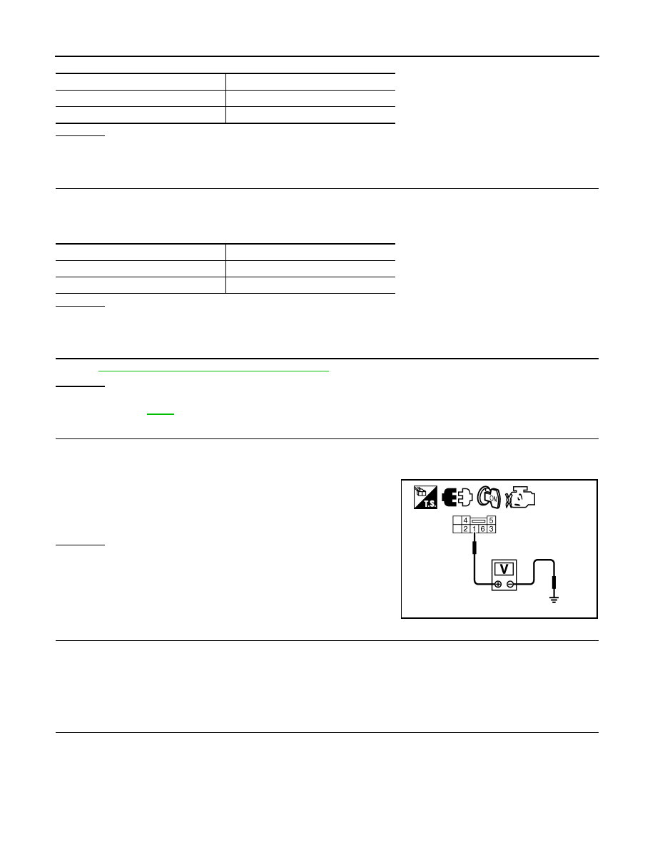
CHECK SNOW MODE SWITCH POWER SUPPLY CIRCUIT
1.
Turn ignition switch OFF.
2.
Disconnect snow mode switch harness connector.
3.
Turn ignition switch ON.
4.
Check voltage between snow mode switch terminal 1 and
ground with CONSULT-III or tester.
OK or NG
OK
>> GO TO 6.
NG
>> GO TO 5.
5.
DETECT MALFUNCTIONING PART
Check the following.
• 10A fuse
• Harness for open or short between snow mode switch and fuse.
>> Repair open circuit or short to ground or short to power in harness or connectors.
6.
CHECK SNOW MODE SWITCH INPUT SIGNAL CIRCUIT FOR OPEN AND SHORT
1.
Turn ignition switch OFF.
2.
Disconnect “unified meter and A/C amp.” harness connector.
3.
Check harness continuity between snow mode switch terminal 4 and “unified meter and A/C amp.” termi-
nal 12. Refer to Wiring Diagram.
CONDITION
INDICATION
Snow mode switch: ON
ON
Snow mode switch: OFF
OFF
CONDITION
INDICATOR LAMP
Snow mode switch: ON
Illuminated
Snow mode switch: OFF
Not illuminated
Voltage: Battery voltage.
PBIB2562E
Continuity should exist.
Нет комментариевНе стесняйтесь поделиться с нами вашим ценным мнением.
Текст