Infiniti FX35 / FX45. Manual — part 226
VEHICLE SECURITY (THEFT WARNING) SYSTEM
BL-171
< SERVICE INFORMATION >
C
D
E
F
G
H
J
K
L
M
A
B
BL
N
O
P
TIWM1676E
BL-172
< SERVICE INFORMATION >
VEHICLE SECURITY (THEFT WARNING) SYSTEM
TIWM0551E
VEHICLE SECURITY (THEFT WARNING) SYSTEM
BL-173
< SERVICE INFORMATION >
C
D
E
F
G
H
J
K
L
M
A
B
BL
N
O
P
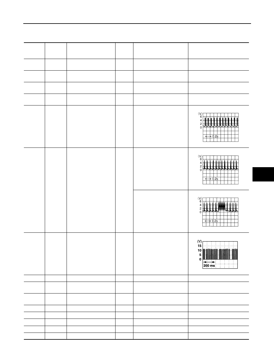
Terminal and Reference Value for BCM
INFOID:0000000001327910
Terminal Wire color
Item
Signal
Input/
output
Condition
Voltage (V)
(Approx.)
11
LG
ACC power supply
(ACC or ON)
Input
Ignition switch (ACC or ON po-
sition)
Battery voltage
12
P/B
Front door switch
passenger side signal
Input
ON (Open)
→
OFF (Closed)
0
→
Battery voltage
13
P/L
Rear door (RH) switch sig-
nal
Input
ON (Open)
→
OFF (Closed)
0
→
Battery voltage
18
B
Remote keyless entry re-
ceiver (Ground)
—
—
0
19
R
Remote keyless entry re-
ceiver (Power supply)
Output
—
20
Y
Remote keyless entry re-
ceiver (Signal)
Input
Stand-by
When remote keyless entry re-
ceiver receives signal from
keyfob.
22
OR
Power window serial link
Input/
Output
IGN SW ON or power window
timer operating
23
G/OR
Security indicator lamp
Output
Goes off
→
Illuminates
Battery voltage
→
0
39
L
CAN-H
Input/
Output
—
—
40
P
CAN-L
Input/
Output
—
—
42
L/R
Power source (Fuse)
Input
—
Battery voltage
49
B
Ground (signal)
—
—
0
52
B
Ground (power)
—
—
0
55
G
Power source (Fusible link)
Input
—
Battery voltage
58
L
Back door switch signal
Input
ON (Open)
→
OFF (Closed)
0
→
9
OCC3881D
OCC3879D
OCC3880D
PIIA2344J

BL-174
< SERVICE INFORMATION >
VEHICLE SECURITY (THEFT WARNING) SYSTEM
Terminal and Reference Value for IPDM E/R
INFOID:0000000001327911
CONSULT-III Function
INFOID:0000000001327912
WORK SUPPORT
DATA MONITOR
62
W
Front door switch
driver side signal
Input
ON (Open)
→
OFF (Closed)
0
→
Battery voltage
63
P
Rear door (LH) switch sig-
nal
Input
ON (Open)
→
OFF (Closed)
0
→
Battery voltage
Terminal Wire
color
Item
Signal
Input/
output
Condition
Voltage (V)
(Approx.)
Terminal Wire
color
Item
Signal
Input/
output
Condition
Voltage (V)
(Approx.)
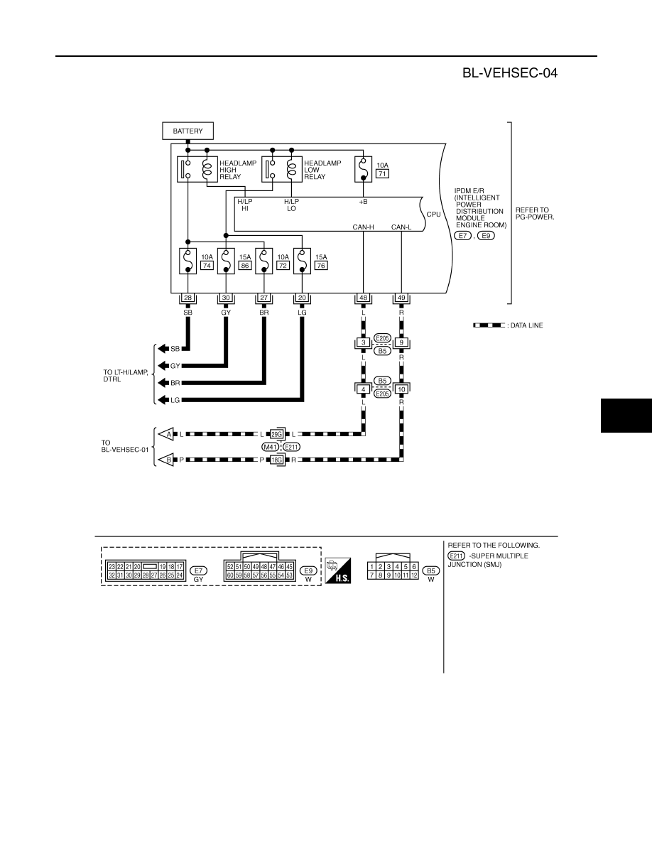
20
LG
Headlamp low (RH)
Output
Lighting switch 2ND position
ON
→
OFF
Battery voltage
→
0
27
BR
Headlamp high (RH)
Output
Lighting switch HIGH or PASS
position
ON
→
OFF
Battery voltage
→
0
28
SB
Headlamp high (LH)
Output
Lighting switch HIGH or PASS
position
ON
→
OFF
Battery voltage
→
0
30
GY
Headlamp low (LH)
Output
Lighting switch 2ND position
ON
→
OFF
Battery voltage
→
0
38
B
Ground (power)
—
—
0
48
L
CAN-H
Input/
Output
—
—
49
R
CAN-L
Input/
Output
—
—
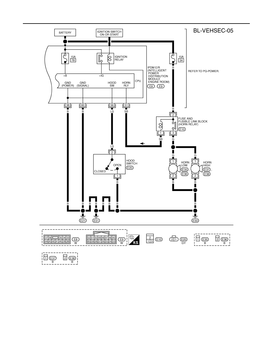
51
SB
Horn relay control signal
Output
Panic alarm is operating
0
Other than above
Battery voltage
56
LG
Hood switch signal
Input
ON (Open)
→
OFF (closed)
0
→
Battery voltage
60
B
Ground (signal)
—
—
0
BCM diagnosis
test item
Check item diagnosis test mode
Content
Theft alm
WORK SUPPORT
Change setting of each function.
DATA MONITOR
Displays the input data of BCM real time.
ACTIVE TEST
Gives a drive signal to a load to check the operation.
Test Item
Description
SECURITY ALARM SET
This mode is able to confirm and change security alarm ON-OFF setting.
THEFT ALM TRG
The switch which triggered vehicle security alarm is recorded. This mode is able to confirm and
erase the record of vehicle security alarm. The trigger data can be erased by touching “CLEAR” on
CONSULT-III screen.
Нет комментариевНе стесняйтесь поделиться с нами вашим ценным мнением.
Текст