Infiniti FX35 / FX45. Manual — part 414
DTC P0550 PSP SENSOR
EC-417
< SERVICE INFORMATION >
[VQ35DE]
C
D
E
F
G
H
I
J
K
L
M
A
EC
N
P
O
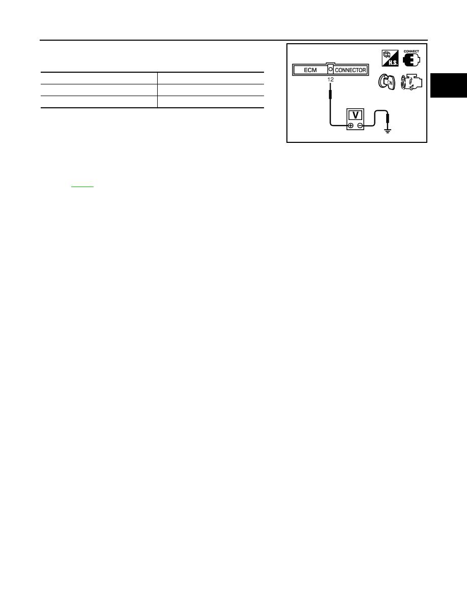
3.
Check voltage between ECM terminal 12 and ground under the
following conditions.
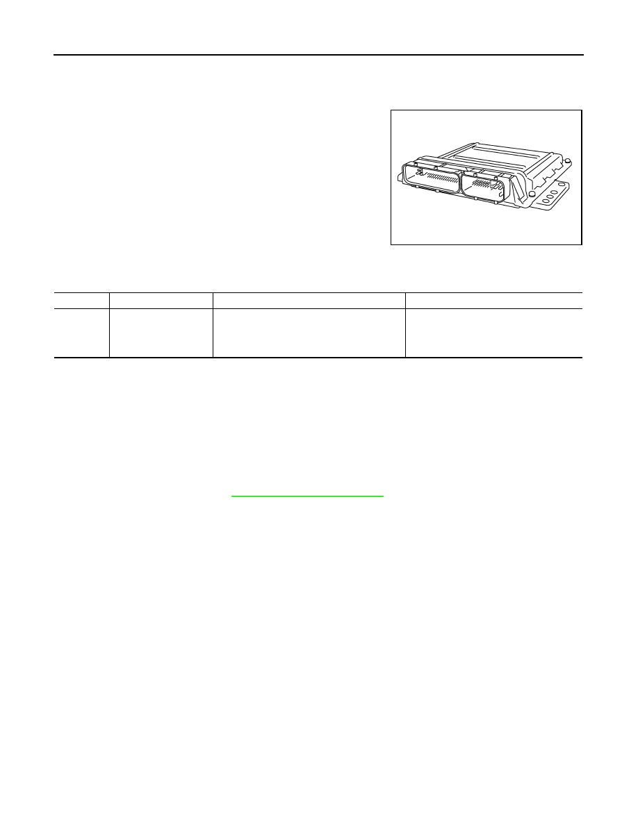
Removal and Installation
INFOID:0000000001326261
POWER STEERING PRESSURE SENSOR
Condition
Voltage
Steering wheel: Being turned
0.5 - 4.5V
Steering wheel: Not being turned
0.4 - 0.8V
MBIB0126E
EC-418
< SERVICE INFORMATION >
[VQ35DE]
DTC P0603 ECM POWER SUPPLY
DTC P0603 ECM POWER SUPPLY
Component Description
INFOID:0000000001326262
Battery voltage is supplied to the ECM even when the ignition switch
is turned OFF for the ECM memory function of the DTC memory, the
air-fuel ratio feedback compensation value memory, the idle air vol-
ume learning value memory, etc.
On Board Diagnosis Logic
INFOID:0000000001326263
DTC Confirmation Procedure
INFOID:0000000001326264
NOTE:
If DTC Confirmation Procedure has been previously conducted, always turn ignition switch OFF and wait at
least 10 seconds before conducting the next test.
1.
Turn ignition switch ON and wait at least 1 second.
2.
Start engine and let it idle for 1 second.
3.
Turn ignition switch OFF, wait at least 10 seconds and then turn ON.
4.
Repeat steps 2 and 3 for four times.
5.
Check 1st trip DTC.
6.
If 1st trip DTC is detected, go to
PBIB1164E
DTC No.
Trouble diagnosis name
DTC detecting condition
Possible cause
P0603
0603
ECM power supply cir-
cuit
ECM back-up RAM system does not function
properly.
• Harness or connectors
[ECM power supply (back-up) circuit is
open or shorted.]
• ECM
DTC P0603 ECM POWER SUPPLY
EC-419
< SERVICE INFORMATION >
[VQ35DE]
C
D
E
F
G
H
I
J
K
L
M
A
EC
N
P
O
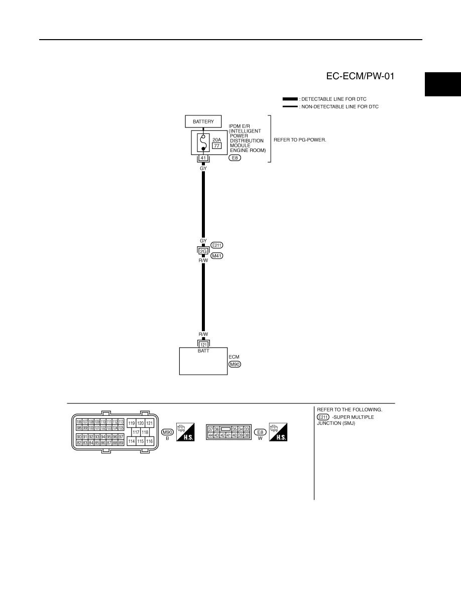
Wiring Diagram
INFOID:0000000001326265
Specification data are reference values and are measured between each terminal and ground.
CAUTION:
Do not use ECM ground terminals when measuring input/output voltage. Doing so may result in dam-
age to the ECM's transistor. Use a ground other than ECM terminals, such as the ground.
TBWM1393E
EC-420
< SERVICE INFORMATION >
[VQ35DE]
DTC P0603 ECM POWER SUPPLY
Diagnosis Procedure
INFOID:0000000001326266
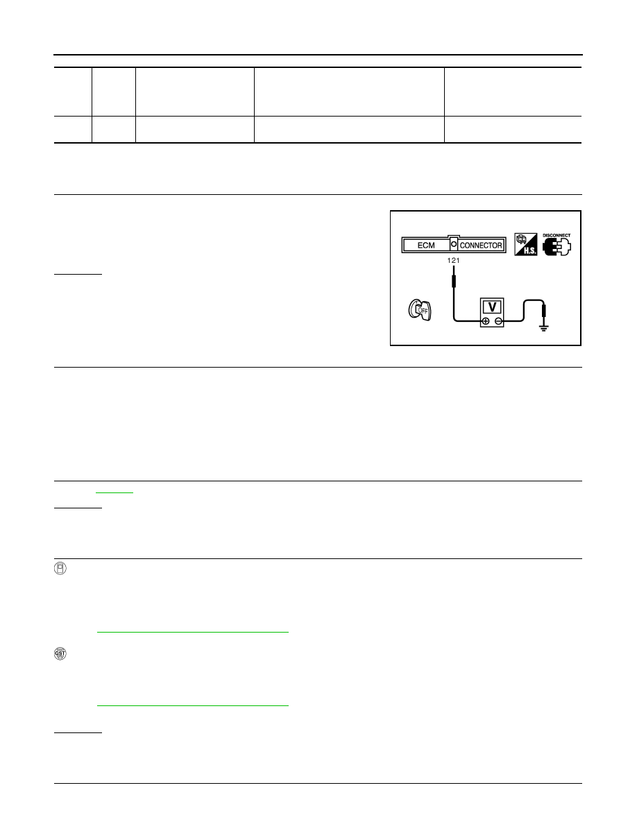
1.
CHECK ECM POWER SUPPLY
1.
Turn ignition switch OFF.
2.
Check voltage between ECM terminal 121 and ground with
CONSULT-III or tester.
OK or NG
OK
>> GO TO 3.
NG
>> GO TO 2.
2.
DETECT MALFUNCTIONING PART
Check the following.
• Harness connector E211, M41
• 20A fuse
• IPDM E/R harness connector E8
• Harness for open or short between ECM and IPDM E/R
>> Repair open circuit or short to ground or short to power in harness or connectors.
3.
CHECK INTERMITTENT INCIDENT
OK or NG
OK
>> GO TO 4.
NG
>> Repair or replace harness or connectors.
4.
PERFORM DTC CONFIRMATION PROCEDURE
With CONSULT-III
1.
Turn ignition switch ON.
2.
Select “SELF DIAG RESULTS” mode with CONSULT-III.
3.
Touch “ERASE”.
4.
Perform DTC Confirmation Procedure.
See
EC-418, "DTC Confirmation Procedure"
5.
Is the 1st trip DTC P0603 displayed again?
With GST
1.
Turn ignition switch ON.
2.
Select Service $04 with GST.
3.
Perform DTC Confirmation Procedure.
See
EC-418, "DTC Confirmation Procedure"
4.
Is the 1st trip DTC P0603 displayed again?
Yes or No
Yes
>> GO TO 5.
No
>> INSPECTION END
5.
REPLACE ECM
TER-
MI-
NAL
NO.
WIRE
COLOR
ITEM
CONDITION
DATA (DC Voltage)
121
R/W
Power supply for ECM
(Back-up)
[Ignition switch OFF]
BATTERY VOLTAGE
(11 - 14V)
Voltage: Battery voltage
MBIB0026E
Нет комментариевНе стесняйтесь поделиться с нами вашим ценным мнением.
Текст