Infiniti FX35 / FX45. Manual — part 562

DTC P0643 SENSOR POWER SUPPLY
EC-1009
< SERVICE INFORMATION >
[VK45DE]
C
D
E
F
G
H
I
J
K
L
M
A
EC
N
P
O
DTC P0643 SENSOR POWER SUPPLY
On Board Diagnosis Logic
INFOID:0000000001326868
This self-diagnosis has the one trip detection logic.
FAIL-SAFE MODE
When the malfunction is detected, ECM enters fail-safe mode and the MIL lights up.
DTC Confirmation Procedure
INFOID:0000000001326869
NOTE:
If DTC Confirmation Procedure has been previously conducted, always turn ignition switch OFF and wait at
least 10 seconds before conducting the next test.
TESTING CONDITION:
Before performing the following procedure, confirm that battery voltage is more than 10V at idle.
1.
Start engine and let it idle for 1 second.
2.
Check DTC.
3.
If DTC is detected, go to
EC-1011, "Diagnosis Procedure"
.
DTC No.
Trouble diagnosis
name
DTC detecting condition
Possible cause
P0643
0643
Sensor power supply
circuit short
ECM detects a voltage of power source for
sensor is excessively low or high.
• Harness or connectors
(APP sensor 1 circuit is shorted.)
(EVAP control system pressure sensor is
shorted.)
(Refrigerant pressure sensor circuit is short-
ed.)
(PSP sensor circuit is shorted.)
• Accelerator pedal position sensor
• EVAP control system pressure sensor
• Refrigerant pressure sensor
• Power steering pressure sensor
Engine operation condition in fail-safe mode
ECM stops the electric throttle control actuator control, throttle valve is maintained at a fixed opening (approx. 5 degrees) by the return
spring.

EC-1010
< SERVICE INFORMATION >
[VK45DE]
DTC P0643 SENSOR POWER SUPPLY
Wiring Diagram
INFOID:0000000001326870
Specification data are reference values and are measured between each terminal and ground.
CAUTION:
Do not use ECM ground terminals when measuring input/output voltage. Doing so may result in dam-
age to the ECM's transistor. Use a ground other than ECM terminals, such as the ground.
TBWM1350E
DTC P0643 SENSOR POWER SUPPLY
EC-1011
< SERVICE INFORMATION >
[VK45DE]
C
D
E
F
G
H
I
J
K
L
M
A
EC
N
P
O
Diagnosis Procedure
INFOID:0000000001326871
1.
CHECK GROUND CONNECTIONS
1.
Turn ignition switch OFF.
2.
Loosen and retighten three ground screws on the body.
Refer to
OK or NG
OK
>> GO TO 2.
NG
>> Repair or replace ground connections.
TER-
MI-
NAL
NO.
WIRE
COLOR
ITEM
CONDITION
DATA (DC Voltage)
48
L
Sensor power supply
(EVAP control system pres-
sure sensor)
[Ignition switch: ON]
Approximately 5V
49
PU
Sensor power supply
(Refrigerant pressure sen-
sor)
[Ignition switch: ON]
Approximately 5V
68
SB
Sensor power supply
(Power steering pressure
sensor)
[Ignition switch: ON]
Approximately 5V
82
B/W
Sensor ground
(APP sensor 1 / ICC steering
switch / ASCD steering
switch)
[Engine is running]
• Warm-up condition
• Idle speed
Approximately 0V
83
G/OR
Sensor ground
(APP sensor 2)
[Engine is running]
• Warm-up condition
• Idle speed
Approximately 0V
90
L/B
Sensor power supply
(APP sensor 1)
[Ignition switch: ON]
Approximately 5V
91
G
Sensor power supply
(APP sensor 2)
[Ignition switch: ON]
Approximately 5V
98
Y/R
Accelerator pedal position
sensor 2
[Ignition switch: ON]
• Engine stopped
• Accelerator pedal: Fully released
0.15 - 0.60V
[Ignition switch: ON]
• Engine stopped
• Accelerator pedal: Fully depressed
1.95 - 2.40V
106
OR
Accelerator pedal position
sensor 1
[Ignition switch: ON]
• Engine stopped
• Accelerator pedal: Fully released
0.5 - 1.0V
[Ignition switch: ON]
• Engine stopped
• Accelerator pedal: Fully depressed
3.9 - 4.7V
PBIB2195E
EC-1012
< SERVICE INFORMATION >
[VK45DE]
DTC P0643 SENSOR POWER SUPPLY
2.
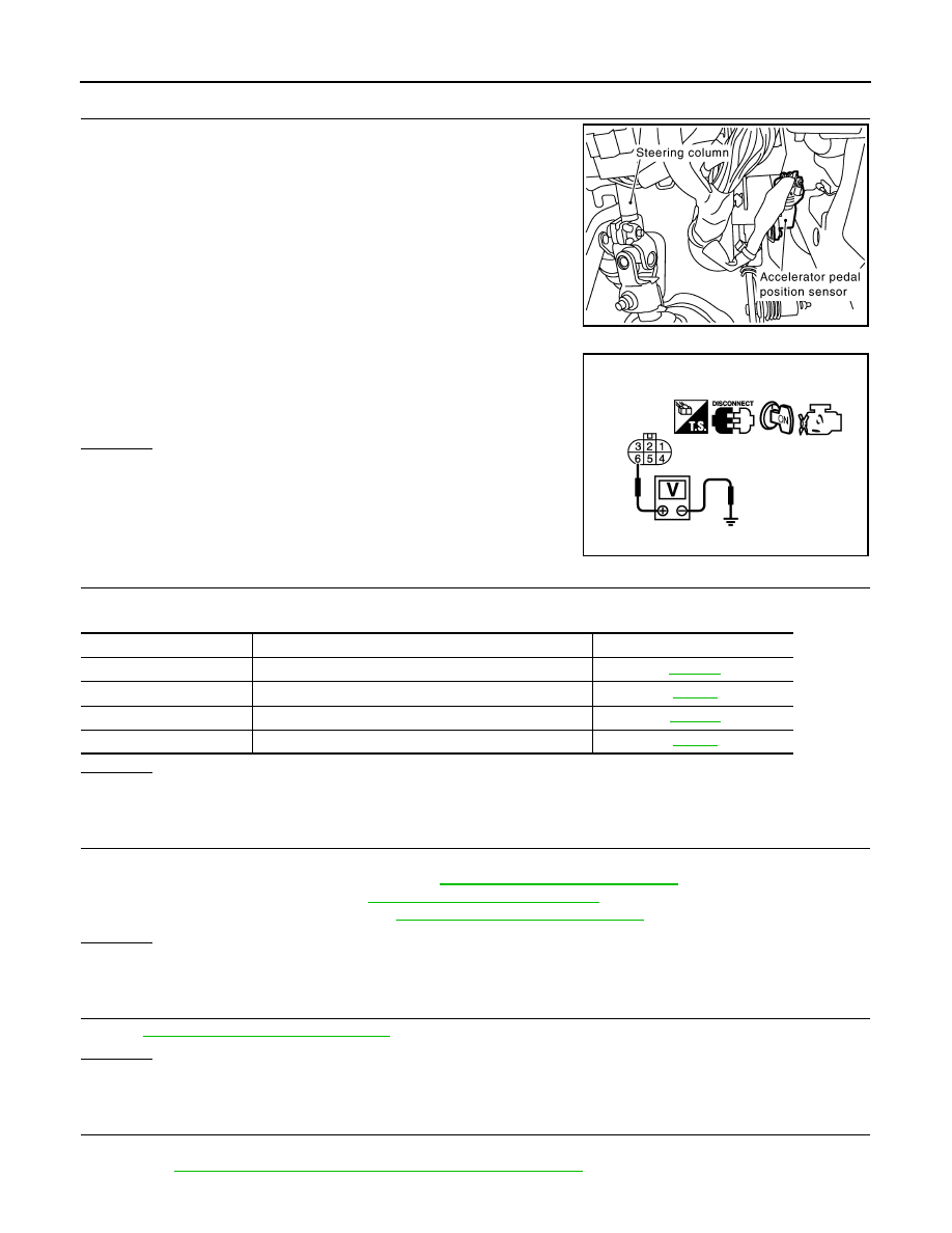
CHECK ACCELERATOR PEDAL POSITION SENSOR 1 POWER SUPPLY CIRCUIT
1.
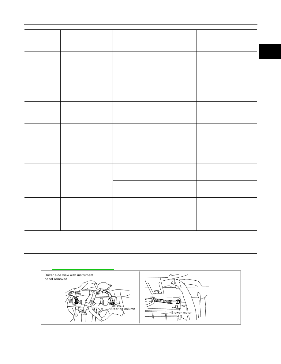
Disconnect accelerator pedal position (APP) sensor harness
connector.
2.
Turn ignition switch ON.
3.
Check voltage between APP sensor terminal 6 and ground with
CONSULT-III or tester.
OK or NG
OK
>> GO TO 5.
NG
>> GO TO 3.
3.
CHECK SENSOR POWER SUPPLY CIRCUITS
Check harness for short to power and short to ground, between the following terminals.
OK or NG
OK
>> GO TO 4.
NG
>> Repair short to ground or short to power in harness or connectors.
4.
CHECK COMPONENTS
Check the following.
• EVAP control system pressure sensor (Refer to
EC-965, "Component Inspection"
.)
• Refrigerant pressure sensor (Refer to
ATC-69, "Magnet Clutch Circuit"
.)
• Power steering pressure sensor (Refer to
EC-1002, "Component Inspection"
.)
OK or NG
OK
>> GO TO 7.
NG
>> Replace malfunctioning component.
5.
CHECK APP SENSOR
EC-1109, "Component Inspection"
.
OK or NG
OK
>> GO TO 7.
NG
>> GO TO 6.
6.
REPLACE ACCELERATOR PEDAL ASSEMBLY
1.
Replace accelerator pedal assembly.
2.
EC-662, "Accelerator Pedal Released Position Learning"
PBIB1548E
Voltage: Approximately 5V
PBIB0914E
ECM terminal
Sensor terminal
Reference Wiring Diagram
90
APP sensor terminal 6
48
EVAP control system pressure sensor terminal 3
49
Refrigerant pressure sensor terminal 1
68
PSP sensor terminal 1
Нет комментариевНе стесняйтесь поделиться с нами вашим ценным мнением.
Текст