Infiniti FX35 / FX45. Manual — part 802
COMBINATION SWITCH
LT-103
< SERVICE INFORMATION >
C
D
E
F
G
H
I
J
L
M
A
B
LT
N
O
P
CONSULT-III Functions (BCM)
INFOID:0000000001328367
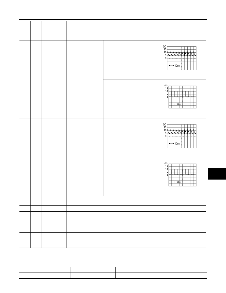
CONSULT-III can display each diagnostic item using the diagnostic test mode shown following.
35
W/G
Combination
switch output 2
ON
Lighting, turn,
wiper switch
(Wiper inter-
mittent dial po-
sition 4)
OFF
Approx. 7.2 V
Any of the conditions below
• Lighting switch 2ND
• Lighting switch PASSING
(Operates only PASSING switch)
• Front wiper switch INT
• Front wiper switch HI
Approx. 1.2 V
36
W/R
Combination
switch output 1
ON
Lighting, turn,
wiper switch
(Wiper inter-
mittent dial po-
sition 4)
OFF
Approx. 7.2 V
Any of the conditions below
• Turn signal switch to right
• Turn signal switch to left
• Front wiper switch MIST
• Front wiper switch LO
• Front washer switch
Approx. 1.2 V
38
W/L
Ignition switch
(ON)
ON
—
Battery voltage
39
L
CAN
−
H
—
—
—
40
P
CAN
−
L
—
—
—
42
L/R
Battery power
supply
OFF
—
Battery voltage
49
B
Ground
ON
—
Approx. 0 V
52
B
Ground
ON
—
Approx. 0 V
55
G
Battery power
supply
OFF
—
Battery voltage
Ter-
mi-
nal
No.
Wire
color
Signal name
Measuring condition
Reference value
Igni-
tion
switch
Operation or condition
PKIB4960J
PKIB4958J
PKIB4960J
PKIB4958J
BCM diagnosis part
Diagnosis mode
Description
COMB SW
DATA MONITOR
Displays BCM input data in real time.

LT-104
< SERVICE INFORMATION >
COMBINATION SWITCH
CONSULT-III BASIC OPERATION
.
DATA MONITOR
Display Item List
NOTE:
This item is displayed, but cannot be monitored
Combination Switch Inspection
INFOID:0000000001381755
1.
SYSTEM CHECK
Referring to table below, check which system malfunctioning switch belongs to.
>> Check the system to which malfunctioning switch belongs, and then GO TO 2.
2.
SYSTEM CHECK
CONSULT-III DATA MONITOR
1.
Select “COMBI SW” of BCM data monitor item.
2.
Confirm that other switches in malfunctioning system operate normally.
Monitor item
Contents
TURN SIGNAL R
“ON/OFF”
Displays “Turn Right (ON)/Other (OFF)” status, determined from lighting switch signal.
TURN SIGNAL L
“ON/OFF”
Displays “Turn Left (ON)/Other (OFF)” status, determined from lighting switch signal.
HI BEAM SW
“ON/OFF”
Displays status (high beam switch: ON/Others: OFF) of high beam switch judged from lighting switch
signal.
HEAD LAMP SW 1
“ON/OFF”
Displays status (headlamp switch 2: ON/Others: OFF) of headlamp switch 1 judged from lighting
switch signal.
HEAD LAMP SW 2
“ON/OFF”
Displays status (headlamp switch 2: ON/Others: OFF) of headlamp switch 2 judged from lighting
switch signal.
LIGHT SW 1ST
“ON/OFF”
Displays status (lighting switch 1ST or 2ND position: ON/Others: OFF) of lighting switch judged from
lighting switch signal.
PASSING SW
“ON/OFF”
Displays status (flash-to-pass switch: ON/Others: OFF) of flash-to-pass switch judged from lighting
switch signal.
AUTO LIGHT SW
“ON/OFF”
Displays “Auto light switch (ON)/Other (OFF)” status, determined from lighting switch signal.
FR FOG SW
“ON/OFF”
Displays “Front fog lamp switch (ON)/Other (OFF)” status, determined from lighting switch signal.
RR FOG SW
NOTE
“OFF”
—
FR WIPER HI
“ON/OFF”
Displays “Front Wiper HI (ON)/Other (OFF)” status, determined from wiper switch signal.
FR WIPER LOW
“ON/OFF”
Displays “Front Wiper LOW (ON)/Other (OFF)” status, determined from wiper switch signal.
FR WIPER INT
“ON/OFF”
Displays “Front Wiper INT (ON)/Other (OFF)” status, determined from wiper switch signal.
FR WASHER SW
“ON/OFF”
Displays “Front Washer Switch (ON)/Other (OFF)” status, determined from wiper switch signal.
INT VOLUME
“1 – 7”
Displays intermittent operation knob setting (1 – 7), determined from wiper switch signal.
RR WIPER ON
“ON/OFF”
Displays “rear Wiper (ON)/Other (OFF)” status as judged from wiper switch signal.
RR WIPER INT
“ON/OFF”
Displays “rear Wiper INT (ON)/Other (OFF)” status as judged from wiper switch signal.
RR WASHER SW
“ON/OFF”
Displays “rear Washer Switch (ON)/Other (OFF)” status as judged from wiper switch signal.
System 1
System 2
System 3
System 4
System 5
—
FR WASHER
FR WIPER LO
TURN LH
TURN RH
FR WIPER HI
—
FR WIPER INT
PASSING
HEAD LAMP 1
INT VOLUME 1
RR WASHER
—
HEAD LAMP
HI BEAM
RR WIPER INT
INT VOLUME 3
AUTO LIGHT
—
LIGHT SW 1
INT VOLUME 2
RR WIPER ON
—
FR FOG
—
COMBINATION SWITCH
LT-105
< SERVICE INFORMATION >
C
D
E
F
G
H
I
J
L
M
A
B
LT
N
O
P
Example: When the HI BEAM switch is malfunctioning, confirm that “TURN RH”, “HEAD LAMP 1” and
“LIGHT SW 1 ST” in System 5, to which the HI BEAM switch belongs, turn ON-OFF normally.
Without CONSULT-III
Operating combination switch, and confirm that other switches in malfunctioning system operate normally.
Example: When the HI BEAM switch is malfunctioning, confirm that “TURN RH”, “HEAD LAMP 1” and “LIGHT
SW 1 ST” in System 5, to which HI BEAM switch belongs, turn ON-OFF normally.
Check results
Other switches in malfunctioning system operate normally.>>Replace lighting switch or wiper switch.
Other switches in malfunctioning system do not operate normally.>>GO TO 3.
3.
CHECK HARNESS BETWEEN COMBINATION SWITCH AND BCM
1.
Turn ignition switch OFF.
2.
Disconnect BCM connector and combination switch connector.
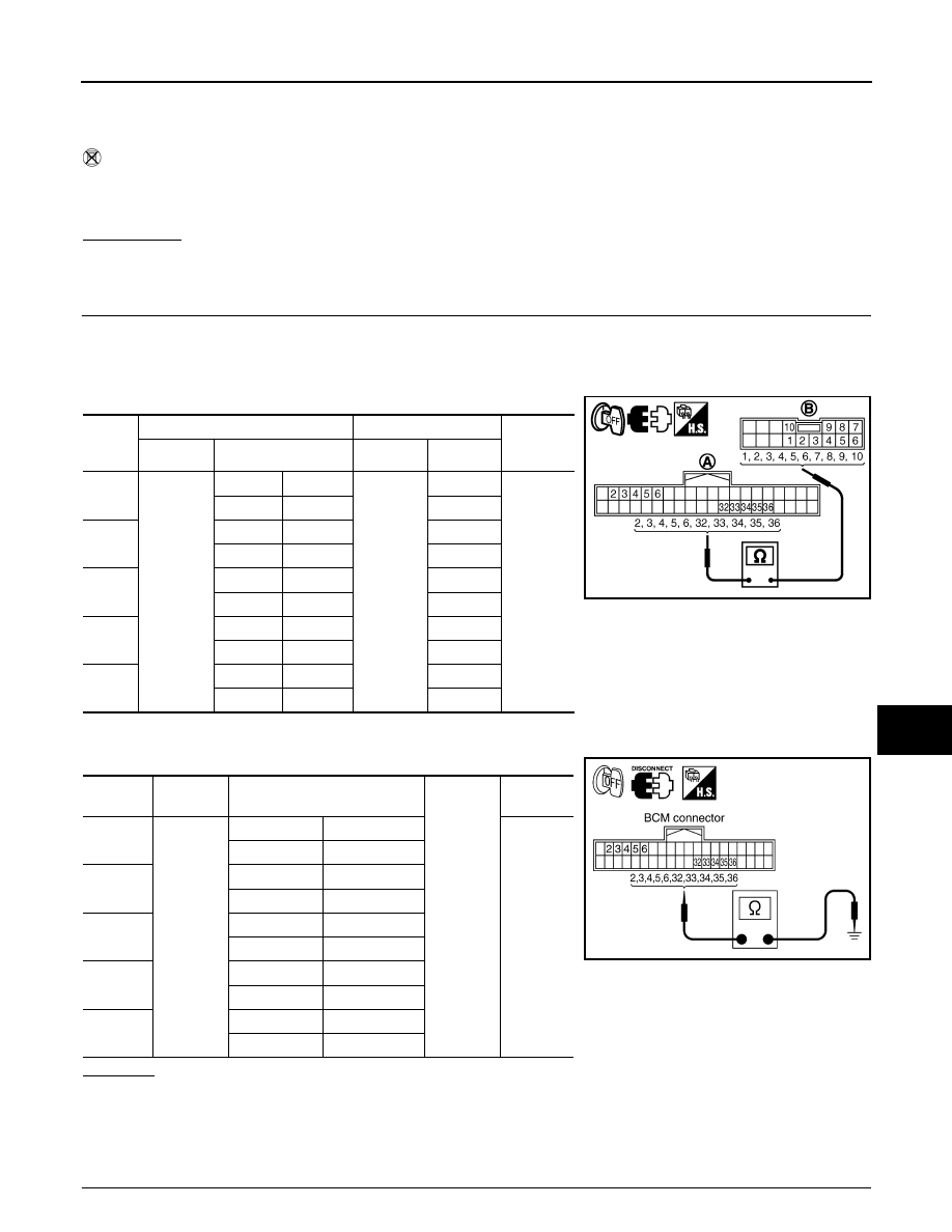
3.
Check for continuity between BCM harness connector (A) of the suspect system and the corresponding
combination switch connector (B).
4.
Check for continuity between each of BCM harness connector in suspect malfunctioning system and
ground.
OK or NG
OK
>>
Check BCM input/output signal of malfunctioning input/output.
• Input: GO TO 4.
• Output: GO TO 5.
NG
>> Repair harness or connector.
4.
CHECK BCM INPUT SIGNAL
Sus-
pect
system
A
B
Continuity
Connector
Terminal
Connector
Terminal
1
M3
Input 1
6
M27
6
Yes
Output 1
36
1
2
Input 2
5
7
Output 2
35
2
3
Input 3
4
10
Output 3
34
3
4
Input 4
3
9
Output 4
33
4
5
Input 5
2
8
Output 5
32
5
Suspect
system
BCM
connector
Terminal
Ground
Continuity
1
M3
Input 1
6
No
Output 1
36
2
Input 2
5
Output 2
35
3
Input 3
4
Output 3
34
4
Input 4
3
Output 4
33
5
Input 5
2
Output 5
32
PKID0105E
PKIA7506E
LT-106
< SERVICE INFORMATION >
COMBINATION SWITCH
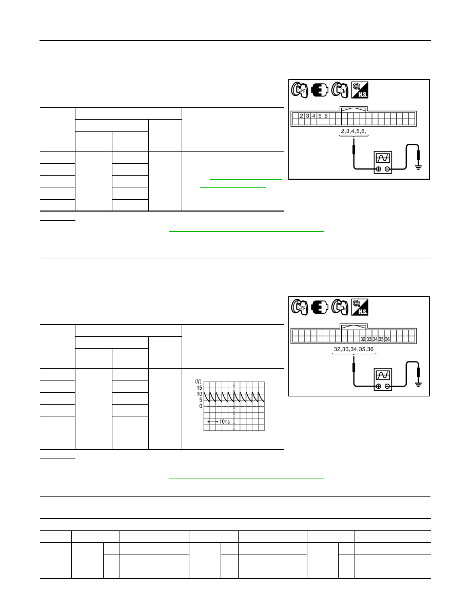
1.
Connect BCM connector and combination switch connector.
2.
Turn ignition switch ON.
3.
Lighting switch and wiper switch are turned OFF.
4.
Set wiper intermittent dial position 4.
5.
Check BCM input terminal voltage waveform of suspect mal-
functioning system.
OK or NG
OK
>> Replace BCM. Refer to
BCS-13, "Removal and Installation of BCM"
.
NG
>> Open circuit in combination switch, GO TO 6.
5.
CHECK BCM OUTPUT SIGNAL
1.
Connect BCM connector and combination switch connector.
2.
Turn ignition switch ON.
3.
Lighting switch and wiper switch are turned OFF.
4.
Set wiper intermittent dial position 4.
5.
Check BCM output terminal voltage waveform of suspect mal-
functioning system.
OK or NG
OK
>> Open circuit in combination switch, GO TO 6.
NG
>> Replace BCM. Refer to
BCS-13, "Removal and Installation of BCM"
.
6.
CHECK COMBINATION SWITCH
Referring to table below, perform combination switch inspection.
Suspect
system
Terminals
Reference value
(+)
(-)
BCM
connector
Terminal
1
M3
6
Ground
2
5
3
4
4
3
5
2
PKID0106E
Suspect
system
Terminals
Reference value
(+)
(-)
BCM
connector
Terminal
1
M3
36
Ground
Approx. 7.0 - 7.5V
2
35
3
34
4
33
5
32
PKID0107E
PKIB4960J
Procedure
1
2
3
4
5
6
7
Re-
place
lighting
switch
Confirm
check
results
OK
INSPECTION END
Confirm
check
results
OK
INSPECTION END
Confirm
check
results
OK
INSPECTION END
NG
Replace wiper switch
NG
Replace switch base
NG
Confirm symptom again
Нет комментариевНе стесняйтесь поделиться с нами вашим ценным мнением.
Текст