Infiniti FX35 / FX45. Manual — part 641
TIMING CHAIN
EM-81
< SERVICE INFORMATION >
[VQ35DE]
C
D
E
F
G
H
I
J
K
L
M
A
EM
N
P
O
b.
Apply a continuous bead of liquid gasket with the tube presser
(commercial service tool) to intake valve timing control covers as
shown in the figure.
Use Genuine RTV Silicone Sealant or equivalent. Refer to
GI-44, "Recommended Chemical Product and Sealant"
c.
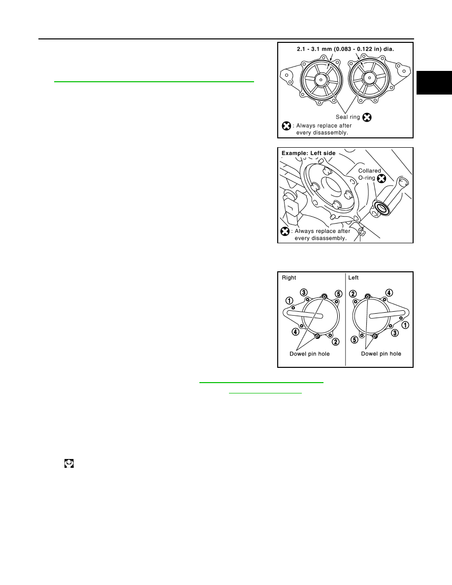
Install new collared O-rings in front timing chain case oil hole
(left and right sides).
d.
Being careful not to move seal ring from the installation groove, align dowel pins on front timing chain
case with holes to install intake valve timing control covers.
e.
Tighten mounting bolts in numerical order as shown in the fig-
ure.
16. Install oil pans (upper and lower). Refer to
EM-30, "Component (2WD Models)"
.
17. Install rocker covers (right and left banks). Refer to
18. Install crankshaft pulley as follows:
a.
Fix crankshaft using the ring gear stopper [SST: KV10117700 (J44716)].
b.
Install crankshaft pulley, taking care not to damage front oil seal.
• When press-fitting crankshaft pulley with plastic hammer, tap on its center portion (not circumference).
c.
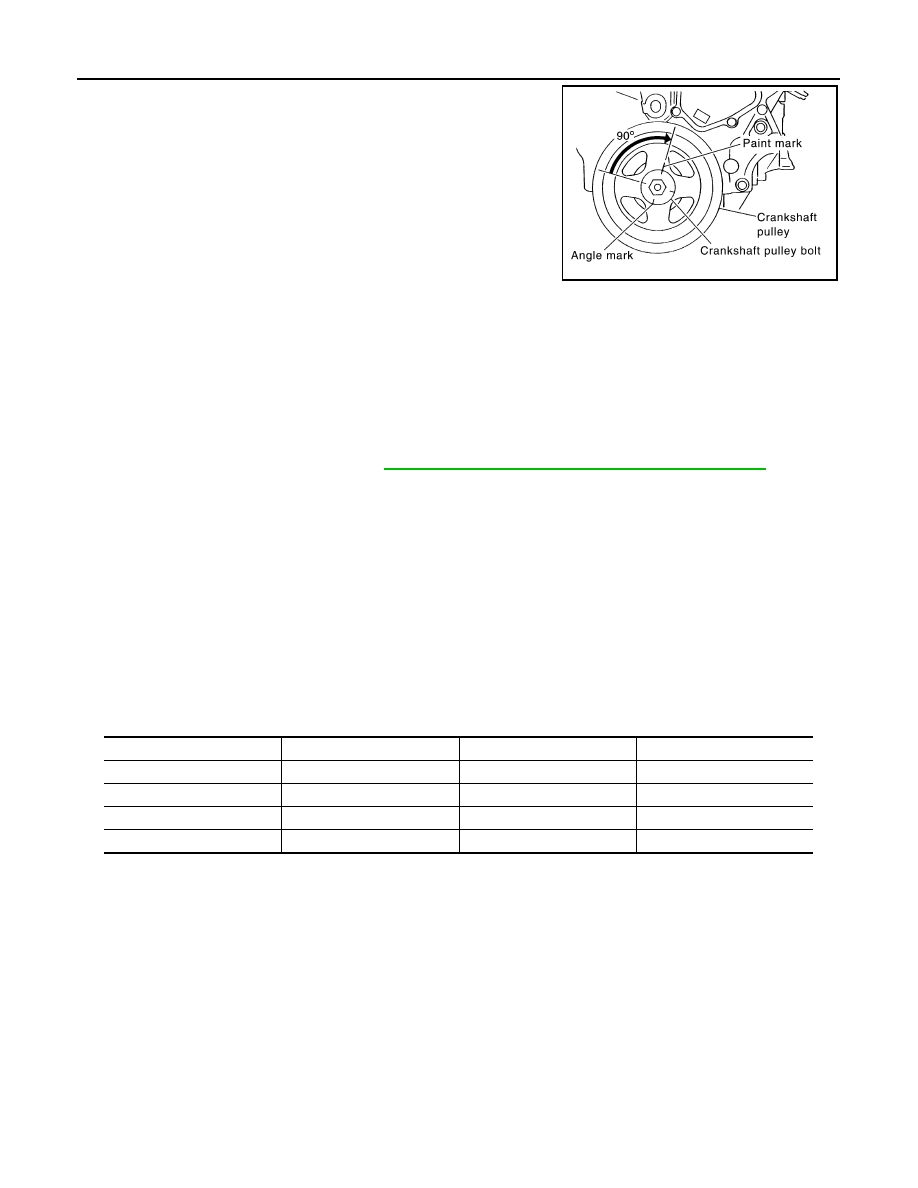
Tighten crankshaft pulley bolt.
d.
Put a paint mark on crankshaft pulley aligning with angle mark on crankshaft pulley bolt.
SBIA0492E
PBIC2631E
PBIC0918E
: 44.1 N·m (4.5 kg-m, 33 ft-lb)
EM-82
< SERVICE INFORMATION >
[VQ35DE]
TIMING CHAIN
e.
Further tighten by 90 degrees. (Angle tightening)
• Check the tightening angle by referencing to the notches. The
angle between two notches is 90 degrees.
19. Rotate crankshaft pulley in normal direction (clockwise when viewed from front) to confirm it turns
smoothly.
20. For the following operations, perform steps in the reverse order of removal.
INSPECTION AFTER INSTALLATION
Inspection for Leaks
The following are procedures for checking fluids leak, lubricates leak.
• Before starting engine, check oil/fluid levels including engine coolant and engine oil. If less than required
quantity, fill to the specified level. Refer to
GI-44, "Recommended Chemical Product and Sealant"
• Use procedure below to check for fuel leakage.
- Turn ignition switch “ON” (with engine stopped). With fuel pressure applied to fuel piping, check for fuel leak-
age at connection points.
- Start engine. With engine speed increased, check again for fuel leakage at connection points.
• Run engine to check for unusual noise and vibration.
NOTE:
If hydraulic pressure inside chain tensioner drops after removal/installation, slack in guide may generate a
pounding noise during and just after the engine start. However, this does not indicate an unusualness. Noise
will stop after hydraulic pressure rises.
• Warm up engine thoroughly to make sure there is no leakage of fuel, or any oil/fluids including engine oil and
engine coolant.
• Bleed air from lines and hoses of applicable lines, such as in cooling system.
• After cooling down engine, again check oil/fluid levels including engine oil and engine coolant. Refill to the
specified level, if necessary.
Summary of the inspection items:
*: Transmission/transaxle/CVT fluid. power steering fluid, brake fluid, etc.
PBIC4821E
Items
Before starting engine
Engine running
After engine stopped
Engine coolant
Level
Leakage
Level
Engine oil
Level
Leakage
Level
Other oils and fluid*
Level
Leakage
Level
Fuel
Leakage
Leakage
Leakage
CAMSHAFT
EM-83
< SERVICE INFORMATION >
[VQ35DE]
C
D
E
F
G
H
I
J
K
L
M
A
EM
N
P
O
CAMSHAFT
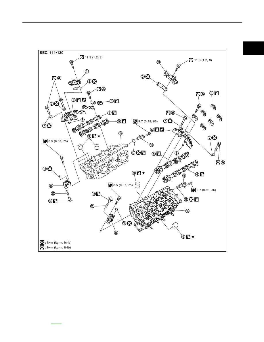
Component
INFOID:0000000001325731
1.
Intake valve timing control solenoid
valve (right bank)
2.
Gasket
3.
Camshaft bracket (No. 2 to 4)
4.
Camshaft (EXH)
5.
Camshaft (INT)
6.
Camshaft bracket (No. 1)
7.
Seal washer
8.
Dowel pin
9.
Valve lifter
10. O-ring
11.
Timing chain tensioner (secondary)
(right bank)
12. Spring
13. Plunger
14.
Timing chain tensioner (secondary)
(left bank)
15. Cylinder head (right bank)
16. Cylinder head (left bank)
17.
O-ring
18.
Camshaft position sensor (PHASE)
(right bank)
19.
Camshaft position sensor (PHASE)
(left bank)
20.
Intake valve timing control solenoid
valve (left bank)
A.
Refer to
PBIC4684E
EM-84
< SERVICE INFORMATION >
[VQ35DE]
CAMSHAFT
• Refer to
for symbols in the figure.
Removal and Installation
INFOID:0000000001325732
REMOVAL
1.
Remove front timing chain case, camshaft sprocket, timing chain and rear timing chain case. Refer to
2.
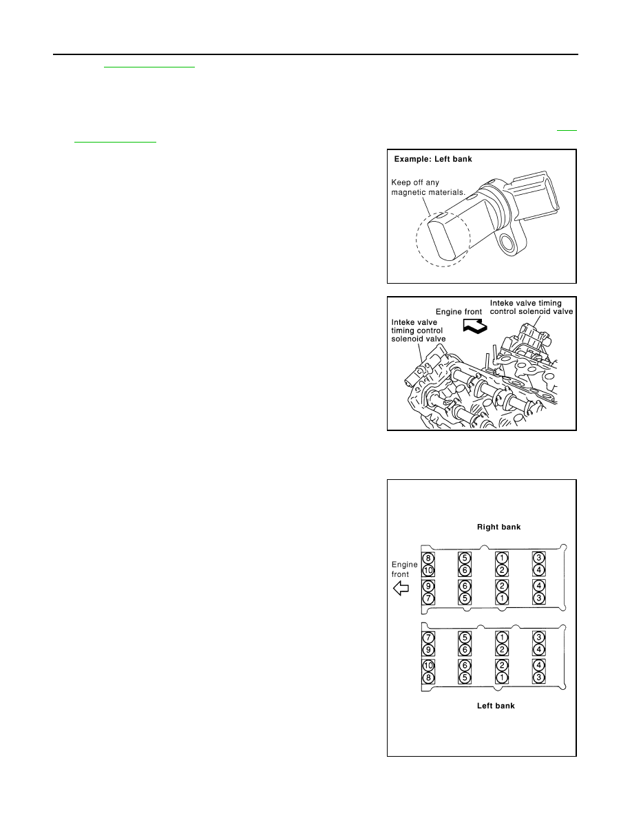
Remove camshaft position sensor (PHASE) (right and left
banks) from cylinder head back side.
CAUTION:
• Handle carefully to avoid dropping and shocks.
• Do not disassemble.
• Do not allow metal powder to adhere to magnetic part at
sensor tip.
• Do not place sensors in a location where they are
exposed to magnetism.
3.
Remove intake valve timing control solenoid valves.
• Discard intake valve timing control solenoid valve gaskets and
use new gaskets for installation.
4.
Remove camshaft brackets.
• Mark camshafts, camshaft brackets and bolts so they are placed in the same position and direction for
installation.
• Equally loosen camshaft bracket bolts in several steps in
reverse order as shown in the figure.
5.
Remove camshaft.
KBIA1046E
SEM443GA
PBIC2050E
Нет комментариевНе стесняйтесь поделиться с нами вашим ценным мнением.
Текст