Infiniti FX35 / FX45. Manual — part 19
AT-4
BRAKE SIGNAL CIRCUIT . . . . . . . ..
CONSULT-III Reference Value in Data Monitor
Mode . . . . . . . . . . . . . . . . . ..
Diagnosis Procedure . . . . . . . . . . . .
A/T INDICATOR CIRCUIT . . . . . . . ...
Description . . . . . . . . . . . . . . . .
CONSULT-III Reference Value in Data Monitor
Mode . . . . . . . . . . . . . . . . . ..
Diagnosis Procedure . . . . . . . . . . . .
TROUBLE DIAGNOSIS FOR SYMPTOMS . .
Wiring Diagram - AT - NONDTC . . . . . . .
A/T Check Indicator Lamp Does Not Come On . .
Engine Cannot Be Started in "P" or "N" Position ...
In "P" Position, Vehicle Moves When Pushed . ...
In "N" Position, Vehicle Moves . . . . . . . ..
Large Shock ("N" to "D" Position) . . . . . . ..
Vehicle Does Not Creep Backward in "R" Position ..
Vehicle Does Not Creep Forward in "D" Position ..
Vehicle Cannot Be Started from D
A/T Does Not Lock-up . . . . . . . . . . ...
A/T Does Not Hold Lock-up Condition . . . . ...
Lock-up Is Not Released . . . . . . . . . ...
Engine Speed Does Not Return to Idle . . . . .
Cannot Be Changed to Manual Mode . . . . ...
Vehicle Does Not Decelerate by Engine Brake . .
SHIFT CONTROL SYSTEM . . . . . . .
Control Device Removal and Installation . . . ...
Control Rod Removal and Installation . . . . ...
Adjustment of A/T Position . . . . . . . . .
Checking of A/T Position . . . . . . . . . ...
A/T SHIFT LOCK SYSTEM . . . . . . . .
Description . . . . . . . . . . . . . . . .
Shift Lock System Electrical Parts Location . . ..
Wiring Diagram - AT - SHIFT . . . . . . . . .
Diagnosis Procedure . . . . . . . . . . . .
KEY INTERLOCK CABLE . . . . . . . ...
Component . . . . . . . . . . . . . . .
Removal and Installation . . . . . . . . . ...
ON-VEHICLE SERVICE . . . . . . . . ...
Control Valve with TCM and A/T Fluid Tempera-
ture Sensor 2 . . . . . . . . . . . . . .
Parking Component (2WD Models Only) . . . ..
Rear Oil Seal . . . . . . . . . . . . . . .
Revolution Sensor Component (2WD Models
Only) . . . . . . . . . . . . . . . . . .
AIR BREATHER HOSE . . . . . . . . .
Removal and Installation . . . . . . . . . ...
TRANSMISSION ASSEMBLY . . . . . . ..
Removal and Installation (2WD Models) . . . ...
Removal and Installation (AWD Models) . . . ..
OVERHAUL . . . . . . . . . . . . . ..
Component . . . . . . . . . . . . . . ...
Oil Channel . . . . . . . . . . . . . . ...
Location of Adjusting Shims, Needle Bearings,
Thrust Washers and Snap Rings . . . . . . ..
DISASSEMBLY . . . . . . . . . . . .
Disassembly . . . . . . . . . . . . . . ..
REPAIR FOR COMPONENT PARTS . . . ..
Oil Pump . . . . . . . . . . . . . . . ...
Front Sun Gear, 3rd One-Way Clutch . . . . ...
Front Carrier, Input Clutch, Rear Internal Gear . .
Mid Sun Gear, Rear Sun Gear, High and Low Re-
verse Clutch Hub . . . . . . . . . . . . ..
High and Low Reverse Clutch . . . . . . . ..
Direct Clutch . . . . . . . . . . . . . . .
ASSEMBLY . . . . . . . . . . . . . ..
Assembly (1) . . . . . . . . . . . . . . .
Adjustment . . . . . . . . . . . . . . .
Assembly (2) . . . . . . . . . . . . . . .
SERVICE DATA AND SPECIFICATIONS
(SDS) . . . . . . . . . . . . . . . .
General Specification . . . . . . . . . . .
Vehicle Speed at Which Gear Shifting Occurs . .
Vehicle Speed at Which Lock-up Occurs/Releas-
es . . . . . . . . . . . . . . . . . . ..
Stall Speed . . . . . . . . . . . . . . .
Line Pressure . . . . . . . . . . . . . .
A/T Fluid Temperature Sensor . . . . . . . ..
Turbine Revolution Sensor . . . . . . . . ...
Vehicle Speed Sensor A/T (Revolution Sensor) ...
Reverse Brake . . . . . . . . . . . . . ..
INDEX FOR DTC
AT-5
< SERVICE INFORMATION >
D
E
F
G
H
I
J
K
L
M
A
B
AT
N
O
P
SERVICE INFORMATION
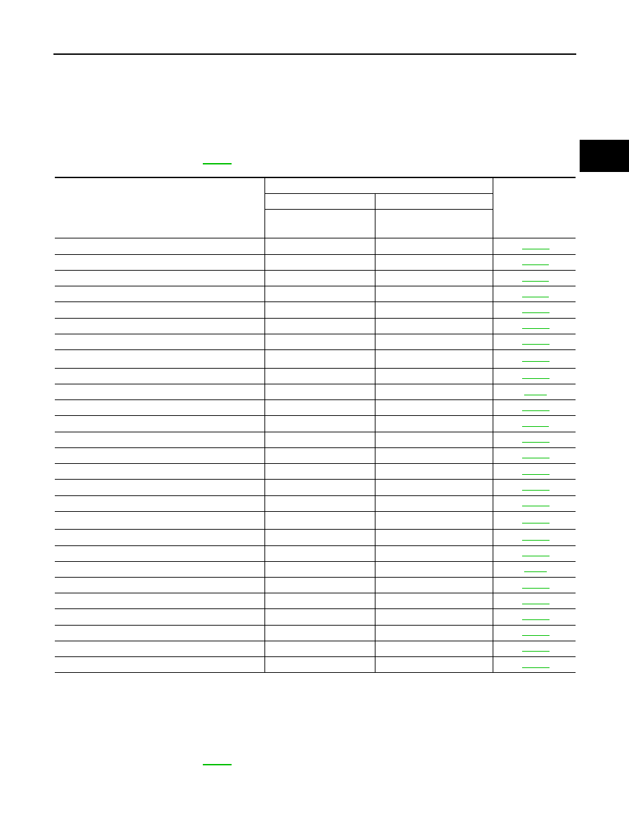
INDEX FOR DTC
Alphabetical Index
INFOID:0000000001327120
NOTE:
If “DTC U1000” is displayed with other DTCs, first perform the trouble diagnosis for “DTC U1000 CAN
COMMUNICATION”. Refer to
*1: These numbers are prescribed by SAE J2012.
*2: These malfunctions cannot be displayed MIL if another malfunction is assigned to MIL.
DTC No. Index
INFOID:0000000001327121
NOTE:
If “DTC U1000” is displayed with other DTCs, first perform the trouble diagnosis for “DTC U1000 CAN
COMMUNICATION”. Refer to
Items
(CONSULT-III screen terms)
DTC
Reference page
OBD-II
Except OBD-II
CONSULT-III
GST
(*1)
CONSULT-III only “TRANS-
MISSION”
A/T 1ST E/BRAKING
—
P1731
ATF 1ST GR FNCTN
P0731
P0731
ATF 2ND GR FNCTN
P0732
P0732
ATF 3RD GR FNCTN
P0733
P0733
ATF 4TH GR FNCTN
P0734
P0734
ATF 5TH GR FNCTN
P0735
P0735
A/T INTERLOCK
P1730
P1730
A/T TCC S/V FNCTN
P0744
(*2)
P0744
ATF TEMP SEN/CIRC
P0710
P1710
CAN COMM CIRCUIT
U1000
U1000
D/C SOLENOID/CIRC
P1762
P1762
ENGINE SPEED SIG
P0725
P0725
FR/B SOLENOID/CIRC
P1757
P1757
HLR/C SOL/CIRC
P1767
P1767
I/C SOLENOID/CIRC
P1752
P1752
L/PRESS SOL/CIRC
P0745
P0745
LC/B SOLENOID/CIRC
P1772
P1772
LC/B SOLENOID FNCT
P1774
(*2)
P1774
MANU MODE SW/CIRC
—
P1815
PNP SW/CIRC
P0705
P0705
STARTER RELAY/CIRC
—
P0615
TCC SOLENOID/CIRC
P0740
P0740
TCM
P0700
P0700
TP SEN/CIRC A/T
P1705
P1705
TURBINE REV S/CIRC
P0717
P0717
VEH SPD SE/CIR-MTR
—
P1721
VEH SPD SEN/CIR AT
P0720
P0720

AT-6
< SERVICE INFORMATION >
INDEX FOR DTC
*1: These numbers are prescribed by SAE J2012.
*2: These malfunctions cannot be displayed MIL if another malfunction is assigned to MIL.
DTC
Items
(CONSULT-III screen terms)
Reference page
OBD-II
Except OBD-II
CONSULT-III
GST
(*1)
CONSULT-III
only “TRANSMIS-
SION”
—
P0615
STARTER RELAY/CIRC
P0700
P0700
TCM
P0705
P0705
PNP SW/CIRC
P0710
P1710
ATF TEMP SEN/CIRC
P0717
P0717
TURBINE REV S/CIRC
P0720
P0720
VEH SPD SEN/CIR AT
P0725
P0725
ENGINE SPEED SIG
P0731
P0731
A/T 1ST GR FNCTN
P0732
P0732
A/T 2ND GR FNCTN
P0733
P0733
A/T 3RD GR FNCTN
P0734
P0734
A/T 4TH GR FNCTN
P0735
P0735
A/T 5TH GR FNCTN
P0740
P0740
TCC SOLENOID/CIRC
P0744
(*2)
P0744
A/T TCC S/V FNCTN
P0745
P0745
L/PRESS SOL/CIRC
P1705
P1705
TP SEN/CIRC A/T
—
P1721
VEH SPD SE/CIR-MTR
P1730
P1730
A/T INTERLOCK
—
P1731
A/T 1ST E/BRAKING
P1752
P1752
I/C SOLENOID/CIRC
P1757
P1757
FR/B SOLENOID/CIRC
P1762
P1762
D/C SOLENOID/CIRC
P1767
P1767
HLR/C SOL/CIRC
P1772
P1772
LC/B SOLENOID/CIRC
P1774
(*2)
P1774
LC/B SOLENOID FNCT
—
P1815
MANU MODE SW/CIRC
U1000
U1000
CAN COMM CIRCUIT
PRECAUTIONS
AT-7
< SERVICE INFORMATION >
D
E
F
G
H
I
J
K
L
M
A
B
AT
N
O
P
PRECAUTIONS
Precaution for Supplemental Restraint System (SRS) "AIR BAG" and "SEAT BELT
PRE-TENSIONER"
INFOID:0000000001612925
The Supplemental Restraint System such as “AIR BAG” and “SEAT BELT PRE-TENSIONER”, used along
with a front seat belt, helps to reduce the risk or severity of injury to the driver and front passenger for certain
types of collision. This system includes seat belt switch inputs and dual stage front air bag modules. The SRS
system uses the seat belt switches to determine the front air bag deployment, and may only deploy one front
air bag, depending on the severity of a collision and whether the front occupants are belted or unbelted.
Information necessary to service the system safely is included in the “SUPPLEMENTAL RESTRAINT SYS-
TEM” and “SEAT BELTS” of this Service Manual.
WARNING:
• To avoid rendering the SRS inoperative, which could increase the risk of personal injury or death in
the event of a collision which would result in air bag inflation, all maintenance must be performed by
an authorized NISSAN/INFINITI dealer.
• Improper maintenance, including incorrect removal and installation of the SRS, can lead to personal
injury caused by unintentional activation of the system. For removal of Spiral Cable and Air Bag
Module, see the “SUPPLEMENTAL RESTRAINT SYSTEM”.
• Do not use electrical test equipment on any circuit related to the SRS unless instructed to in this
Service Manual. SRS wiring harnesses can be identified by yellow and/or orange harnesses or har-
ness connectors.
Precaution for On Board Diagnosis (OBD) System of A/T and Engine
INFOID:0000000001327123
The ECM has an on board diagnostic system. It will light up the malfunction indicator lamp (MIL) to warn the
driver of a malfunction causing emission deterioration.
CAUTION:
• Be sure to turn the ignition switch OFF and disconnect the battery cable from the negative terminal
before any repair or inspection work. The open/short circuit of related switches, sensors, solenoid
valves, etc. Will cause the MIL to light up.
• Be sure to connect and lock the connectors securely after work. A loose (unlocked) connector will
cause the MIL to light up due to an open circuit. (Be sure the connector is free from water, grease,
dirt, bent terminals, etc.)
• Be sure to route and secure the harnesses properly after work. Interference of the harness with a
bracket, etc. May cause the MIL to light up due to a short circuit.
• Be sure to connect rubber tubes properly after work. A misconnected or disconnected rubber tube
may cause the MIL to light up due to a malfunction of the EVAP system or fuel injection system, etc.
• Be sure to erase the unnecessary malfunction information (repairs completed) from the TCM and
ECM before returning the vehicle to the customer.
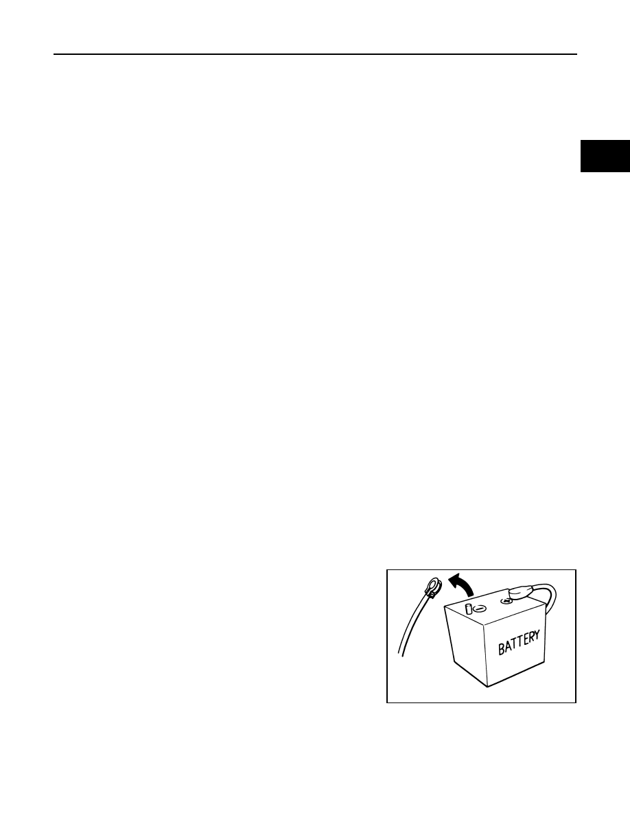
Precaution
INFOID:0000000001327124
• Before connecting or disconnecting the A/T assembly har-
ness connector, turn ignition switch OFF and disconnect the
battery cable from the negative terminal. Because battery
voltage is applied to TCM even if ignition switch is turned
OFF.
SEF289H
Нет комментариевНе стесняйтесь поделиться с нами вашим ценным мнением.
Текст