Infiniti FX35 / FX45. Manual — part 594

DTC P2A00, P2A03 A/F SENSOR 1
EC-1137
< SERVICE INFORMATION >
[VK45DE]
C
D
E
F
G
H
I
J
K
L
M
A
EC
N
P
O
5.
Also check harness for short to power.
OK or NG
OK
>> GO TO 9.
NG
>> Repair open circuit or short to ground or short to power in harness or connectors.
9.
CHECK A/F SENSOR 1 HEATER
EC-744, "Component Inspection"
OK or NG
OK
>> GO TO 10.
NG
>> GO TO 11.
10.
CHECK INTERMITTENT INCIDENT
Perform
OK or NG
OK
>> GO TO 11.
NG
>> Repair or replace.
11.
REPLACE AIR FUEL RATIO (A/F) SENSOR 1
Replace malfunctioning air fuel ratio (A/F) sensor 1.
CAUTION:
• Discard any A/F sensor which has been dropped from a height of more than 0.5 m (19.7 in) onto a
hard surface such as a concrete floor; use a new one.
• Before installing new A/F sensor, clean exhaust system threads using Oxygen Sensor Thread
Cleaner tool J-43897-18 or J-43897-12 and approved anti-seize lubricant.
>> GO TO 12.
12.
CONFIRM A/F ADJUSTMENT DATA
1.
Turn ignition switch ON.
2.
Select “A/F ADJ-B1” and “A/F ADJ-B2” in “DATA MONITOR” mode with CONSULT-III.
3.
Make sure that “0.000” is displayed on CONSULT-III screen.
OK or NG
OK
>> INSPECTION END
NG
>> GO TO 13.
13.
CLEAR THE SELF-LEARNING DATA.
With CONSULT-III
1.
Start engine and warm it up to normal operating temperature.
2.
Select “SELF-LEARNING CONT” in “WORK SUPPORT” mode with CONSULT-III.
3.
Clear the self-learning control coefficient by touching “CLEAR”.
Without CONSULT-III
1.
Start engine and warm it up to normal operating temperature.
2.
Turn ignition switch OFF.
3.
Disconnect mass air flow sensor (1) harness connector.
4.
Restart engine and let it idle for at least 5 seconds.
5.
Stop engine and reconnect mass air flow sensor harness con-
nector.
6.
Make sure DTC P0102 is displayed.
7.
Erase the DTC memory. Refer to
8.
Make sure DTC P0000 is displayed.
>> GO TO 14.
Continuity should not exist.
PBIB3230E
EC-1138
< SERVICE INFORMATION >
[VK45DE]
DTC P2A00, P2A03 A/F SENSOR 1
14.
CONFIRM A/F ADJUSTMENT DATA
1.
Turn ignition switch OFF and then ON.
2.
Select “A/F ADJ-B1” and “A/F ADJ-B2” in “DATA MONITOR” mode with CONSULT-III.
3.
Make sure that “0.000” is displayed on CONSULT-III screen.
>> INSPECTION END
Removal and Installation
INFOID:0000000001327038
AIR FUEL RATIO (A/F) SENSOR 1
.
ASCD BRAKE SWITCH
EC-1139
< SERVICE INFORMATION >
[VK45DE]
C
D
E
F
G
H
I
J
K
L
M
A
EC
N
P
O
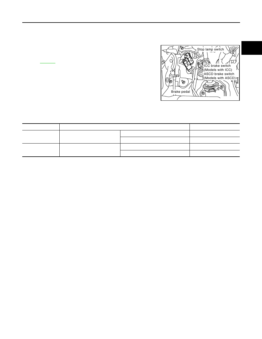
ASCD BRAKE SWITCH
Component Description
INFOID:0000000001327039
When the brake pedal is depressed, ASCD brake switch is turned
OFF and stop lamp switch is turned ON. ECM detects the state of
the brake pedal by this input of two kinds (ON/OFF signal).
Refer to
CONSULT-III Reference Value in Data Monitor Mode
INFOID:0000000001327040
Specification data are reference values.
PBIB2558E
MONITOR ITEM
CONDITION
SPECIFICATION
BRAKE SW1
(ASCD brake switch)
• Ignition switch: ON
Brake pedal: Fully released
ON
Brake pedal: Slightly depressed
OFF
BRAKE SW2
(Stop lamp switch)
• Ignition switch: ON
Brake pedal: Fully released
OFF
Brake pedal: Slightly depressed
ON
EC-1140
< SERVICE INFORMATION >
[VK45DE]
ASCD BRAKE SWITCH
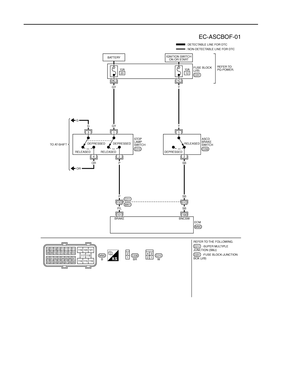
Wiring Diagram
INFOID:0000000001327041
Specification data are reference values and are measured between each terminal and ground.
CAUTION:
Do not use ECM ground terminals when measuring input/output voltage. Doing so may result in dam-
age to the ECM's transistor. Use a ground other than ECM terminals, such as the ground.
TBWM1365E
Нет комментариевНе стесняйтесь поделиться с нами вашим ценным мнением.
Текст