Infiniti FX35 / FX45. Manual — part 602
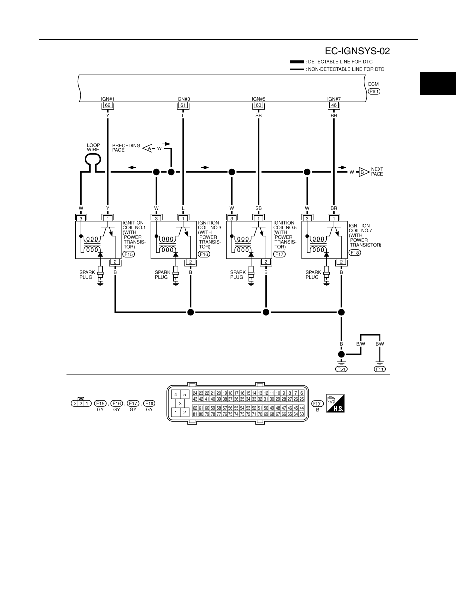
IGNITION SIGNAL
EC-1169
< SERVICE INFORMATION >
[VK45DE]
C
D
E
F
G
H
I
J
K
L
M
A
EC
N
P
O
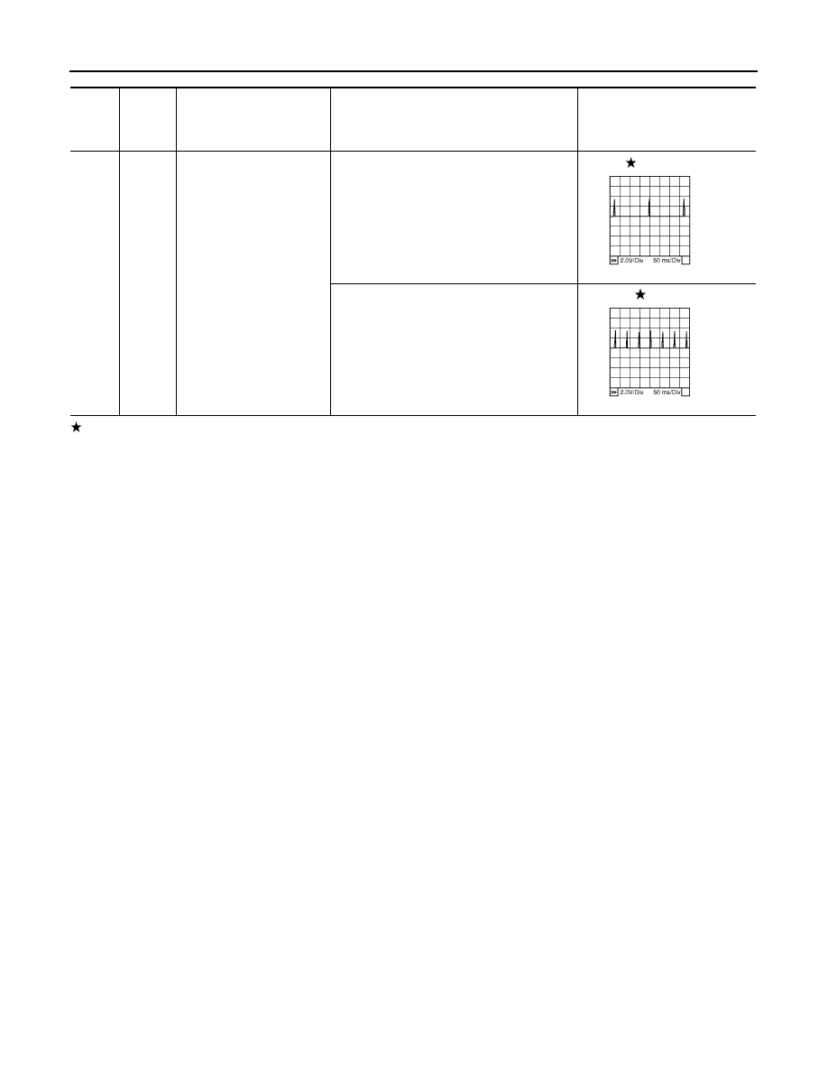
Specification data are reference values and are measured between each terminal and ground.
Pulse signal is measured by CONSULT-III.
CAUTION:
Do not use ECM ground terminals when measuring input/output voltage. Doing so may result in dam-
age to the ECM's transistor. Use a ground other than ECM terminals, such as the ground.
TBWM1360E
EC-1170
< SERVICE INFORMATION >
[VK45DE]
IGNITION SIGNAL
: Average voltage for pulse signal (Actual pulse signal can be confirmed by oscilloscope.)
TER-
MI-
NAL
NO.
WIRE
COLOR
ITEM
CONDITION
DATA (DC Voltage)
46
60
61
62
BR
SB
L
Y
Ignition signal No. 7
Ignition signal No. 5
Ignition signal No. 3
Ignition signal No. 1
[Engine is running]
• Warm-up condition
• Idle speed
NOTE:
The pulse cycle changes depending on rpm
at idle
0 - 0.2V
[Engine is running]
• Warm-up condition
• Engine speed: 2,000 rpm
0.1 - 0.4V
PBIB0044E
PBIB0045E
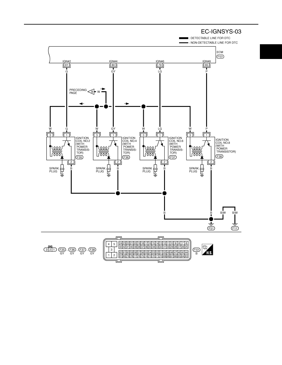
IGNITION SIGNAL
EC-1171
< SERVICE INFORMATION >
[VK45DE]
C
D
E
F
G
H
I
J
K
L
M
A
EC
N
P
O
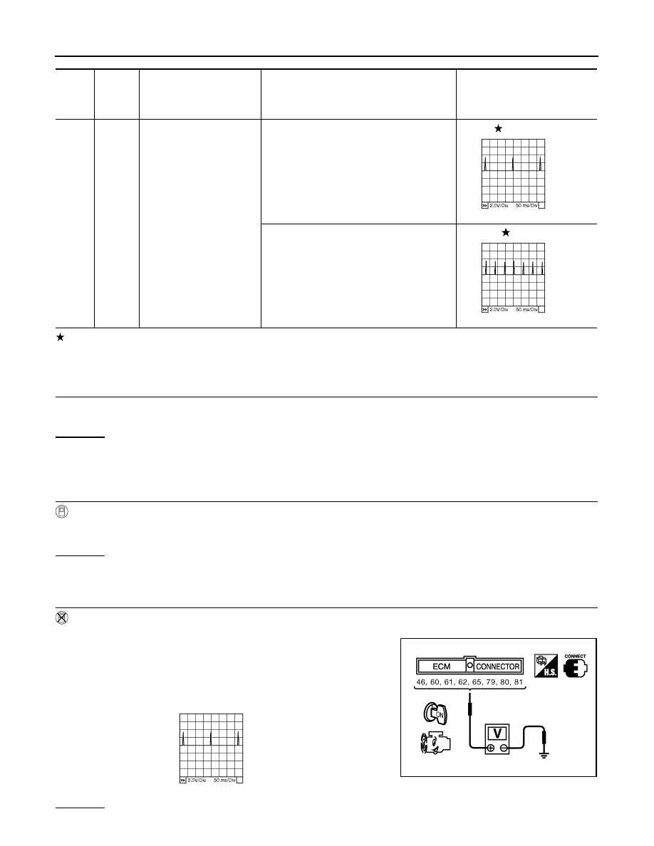
Specification data are reference values and are measured between each terminal and ground.
Pulse signal is measured by CONSULT-III.
CAUTION:
Do not use ECM ground terminals when measuring input/output voltage. Doing so may result in dam-
age to the ECM's transistor. Use a ground other than ECM terminals, such as the ground.
TBWM1361E
EC-1172
< SERVICE INFORMATION >
[VK45DE]
IGNITION SIGNAL
: Average voltage for pulse signal (Actual pulse signal can be confirmed by oscilloscope.)
Diagnosis Procedure
INFOID:0000000001327070
1.
CHECK ENGINE START
Turn ignition switch OFF, and restart engine.
Is engine running?
Yes or No
Yes (With CONSULT-III)>>GO TO 2.
Yes (Without CONSULT-III)>>GO TO 3.
No
>> GO TO 4.
2.
CHECK OVERALL FUNCTION
With CONSULT-III
1.
Perform “POWER BALANCE” in “ACTIVE TEST” mode with CONSULT-III.
2.
Make sure that each circuit produces a momentary engine speed drop.
OK or NG
OK
>> INSPECTION END
NG
>> GO TO 10.
3.
CHECK OVERALL FUNCTION
Without CONSULT-III
1.
Let engine idle.
2.
Read the voltage signal between ECM terminals 46, 60, 61, 62,
65, 79, 80, 81 and ground with an oscilloscope.
3.
Verify that the oscilloscope screen shows the signal wave as
shown below.
NOTE:
The pulse cycle changes depending on rpm at idle.
OK or NG
TER-
MI-
NAL
NO.
WIRE
COLOR
ITEM
CONDITION
DATA (DC Voltage)
65
79
80
81
P
LG
GY
G
Ignition signal No. 8
Ignition signal No. 6
Ignition signal No. 4
Ignition signal No. 2
[Engine is running]
• Warm-up condition
• Idle speed
NOTE:
The pulse cycle changes depending on rpm
at idle
0 - 0.2V
[Engine is running]
• Warm-up condition
• Engine speed: 2,000 rpm
0.1 - 0.4V
PBIB0044E
PBIB0045E
PBIB2094E
PBIB0044E
Нет комментариевНе стесняйтесь поделиться с нами вашим ценным мнением.
Текст