Infiniti FX35 / FX45. Manual — part 889
FRONT OIL SEAL
RFD-11
< SERVICE INFORMATION >
C
E
F
G
H
I
J
K
L
M
A
B
RFD
N
O
P
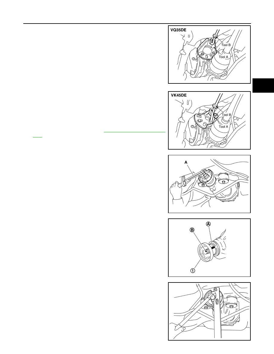
• For VQ35DE models
NOTE:
Circular clip installation position: Final drive side
• For VK45DE models
NOTE:
Circular clip installation position: Final drive side
7.
Remove propeller shaft. Refer to
8.
Measure the total preload with the preload gauge.
NOTE:
Record the preload measurement.
9.
Put matching mark (B) on the end of the drive pinion. The
matching mark (B) should be in line with the matching mark (A)
on companion flange (1).
CAUTION:
For matching mark, use paint. Never damage companion
flange and drive pinion.
NOTE:
The matching mark (A) on the final drive companion flange (1)
indicates the maximum vertical runout position.
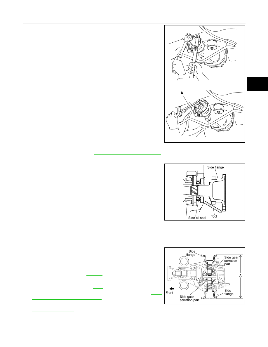
10. Remove drive pinion lock nut using the flange wrench.
Tool number
A: KV40104100 (
—
)
B: ST36230000 (J-25840-A)
SDIA1582E
Tool number
A: KV40101000 (
—
)
B: ST36230000 (J-25840-A)
SDIA1583E
Tool number
A: ST3127S000 (J-25765-A)
PDIA0977E
PDIA0750J
PDIA0978E

RFD-12
< SERVICE INFORMATION >
FRONT OIL SEAL
11. Remove companion flange using a puller.
12. Remove front oil seal using the puller.
INSTALLATION
1.
Apply multi-purpose grease to front oil seal lips.
2.
Install front oil seal using the drift as shown in figure.
CAUTION:
• Never reuse oil seal.
• When installing, never incline oil seal.
3.
Align the matching mark (B) of drive pinion with the matching
mark (A) of companion flange (1), and then install the compan-
ion flange (1).
4.
Apply anti-corrosion oil to the thread and seat of new drive pinion lock nut, and temporarily tighten drive
pinion lock nut to drive pinion.
CAUTION:
Never reuse drive pinion lock nut.
PDIA0979E
Tool number
A: KV381054S0 (J-34286)
PDIA0980E
Tool number
A: ST30720000 (J-25405)
PDIA0752J
PDIA0750J
FRONT OIL SEAL
RFD-13
< SERVICE INFORMATION >
C
E
F
G
H
I
J
K
L
M
A
B
RFD
N
O
P
5.
Tighten to drive pinion lock nut, while adjust total preload torque.
CAUTION:
• Adjust to the lower limit of the drive pinion lock nut tight-
ening torque first.
• If the preload torque exceeds the specified value, replace
collapsible spacer and tighten it again to adjust. Never
loosen drive pinion lock nut to adjust the preload torque.
6.
Make a stamping for identification of front oil seal replacement
frequency. Refer to "IDENTIFICATION STAMP OF REPLACE-
MENT FREQUENCY OF FRONT OIL SEAL".
CAUTION:
Be sure to make a stamping after replacing front oil seal.
7.
Install propeller shaft. Refer to
PR-9, "Removal and Installation"
8.
Install side flange with the following procedure.
a.
Attach the protector to side oil seal.
b.
After the side flange is inserted and the serrated part of side
gear has engaged the serrated part of flange, remove the pro-
tector.
c.
Put a suitable drift on the center of side flange, then drive it until sound changes.
NOTE:
When installation is completed, driving sound of the side flange turns into a sound which seems to affect
the whole final drive.
d.
Confirm that the dimension of the side flange installation (Mea-
surement A) in the figure comes into the following.
9.
Install drive shaft. Refer to
.
10. Install rear wheel sensor. Refer to
11. Install center muffler. Refer to
12. Refill gear oil to the final drive and check oil level. Refer to
9, "Changing Differential Gear Oil"
13. Check the final drive for oil leakage. Refer to
.
Tool number
A: ST3127S000 (J-25765-A)
Drive pinion lock nut tightening torque:
147 - 323 N·m (15 - 32 kg-m, 109 - 238 ft-lb)
Total preload torque:
Total preload torque should equal the measurement tak-
en during removal plus an additional 0.1 - 0.4 N·m (0.01 -
0.04 kg-m, 1 - 3 in-lb).
Tool number
: KV38107900 (J-39352)
PDIA0981E
SDIA0822E
Measurement A: 326 - 328 mm (12.83 - 12.91 in)
SDIA1039E
RFD-14
< SERVICE INFORMATION >
SIDE OIL SEAL
SIDE OIL SEAL
Removal and Installation
INFOID:0000000001327498
REMOVAL
1.
Remove center muffler with a power tool. Refer to
2.
Remove rear wheel sensor. Refer to
.
3.
Remove drive shaft from final drive. Then suspend it by wire etc. Refer to
.
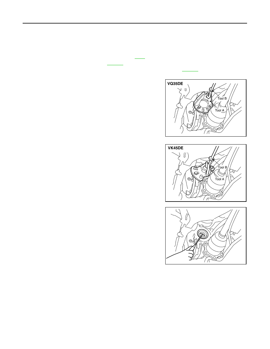
4.
Install attachment to side flange, and then pull out the side flange with the sliding hammer.
• For VQ35DE models
NOTE:
Circular clip installation position: Final drive side
• For VK45DE models
NOTE:
Circular clip installation position: Final drive side
5.
Remove side oil seal, using a flat-bladed screwdriver.
CAUTION:
Be careful not to damage gear carrier.
INSTALLATION
1.
Apply multi-purpose grease to side oil seal lips.
Tool number
A: KV40104100 (
—
)
B: ST36230000 (J-25840-A)
SDIA1582E
Tool number
A: KV40101000 (
—
)
B: ST36230000 (J-25840-A)
SDIA1583E
SDIA1584E
Нет комментариевНе стесняйтесь поделиться с нами вашим ценным мнением.
Текст