Infiniti FX35 / FX45. Manual — part 735
GW-24
< SERVICE INFORMATION >
POWER WINDOW SYSTEM
Terminal and Reference Value for Power Window Main Switch
INFOID:0000000001327969
22
OR
Power window serial link
Input/Output
IGN SW ON or power window
timer operating.
38
W/L
Ignition switch
(ON or START)
Input
Ignition switch
(ON or START position)
Battery voltage
39
L
CAN - H
Input/Output
—
—
40
P
CAN - L
Input/Output
—
—
42
L/R
Power source (Fuse)
Input
—
Battery voltage
49
B
Ground (signal)
—
—
0
52
B
Ground (power)
—
—
0
53
Y/B
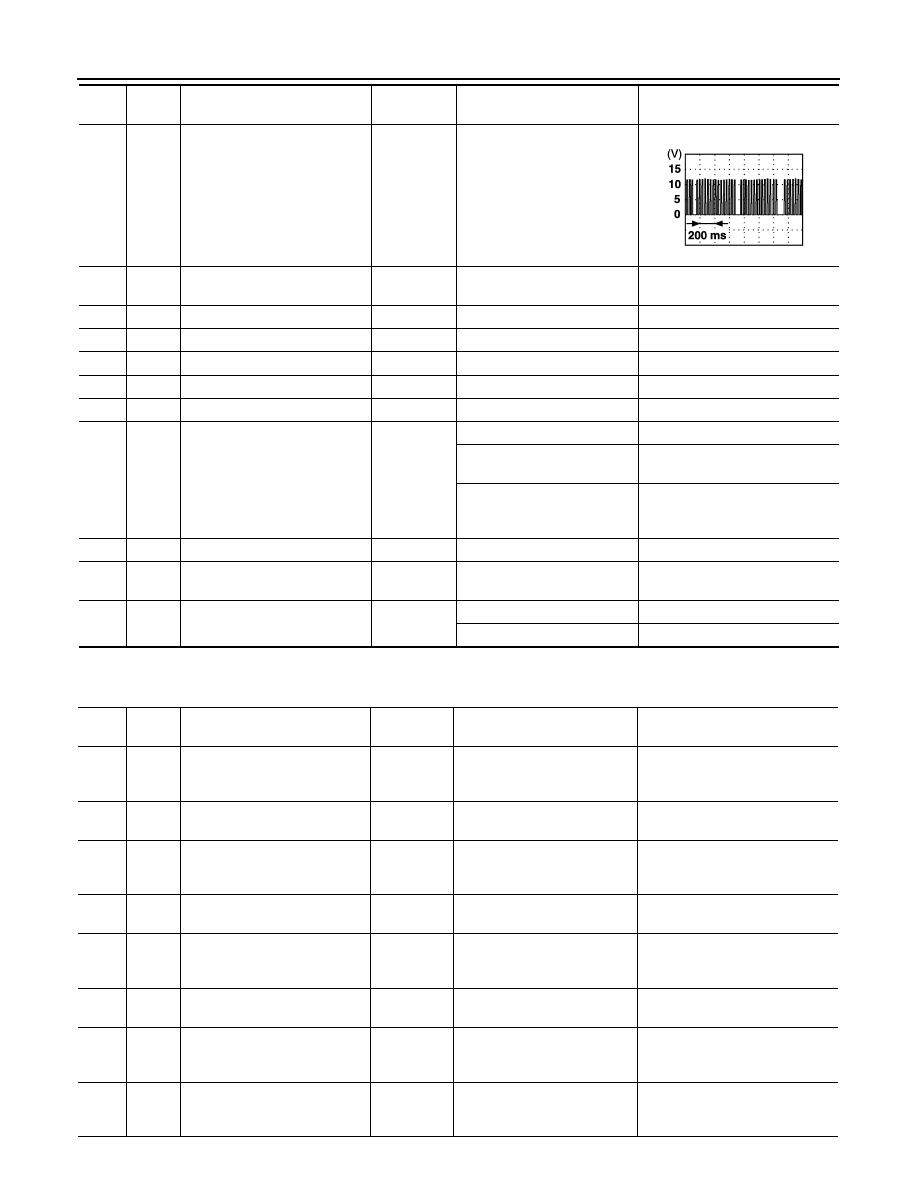
Rap signal
Output
IGN SW ON
Battery voltage
Within 45 second after ignition
switch is turned to OFF
Battery voltage
When driver side or passen-
ger side door is open in power
window timer is operates
0
54
W
Power window power supply
Output
—
Battery voltage
55
G
Power source
(Fusible link)
Input
—
Battery voltage
62
W
Front door switch
driver side signal
Input
ON (Open)
0
OFF (Close)
Battery voltage
Ter-
minal
Wire
color
Item
Signal
Input/Output
Condition
Voltage [V]
(Approx.)
PIIA2344J
Ter-
minal
Wire
color
Item
Signal
Input/Output
Condition
Voltage [V]
(Approx.)
1
Y
Rear LH power window
UP signal
Output
When rear LH switch in
power window main switch is
UP at operated.
Battery voltage
2
SB
Limit switch and encoder
ground
—
—
0
3
R
Rear LH power window
DOWN signal
Output
When rear LH switch in
power window main switch is
DOWN at operated.
Battery voltage
4
P
Door key cylinder switch
LOCK signal
Input
Key position
(Neutral
→
Locked)
5
→
0
5
G
Rear RH power window
DOWN signal
Output
When rear RH switch in
power window main switch is
DOWN at operated.
Battery voltage
6
OR
Door key cylinder switch
UNLOCK signal
Input
Key position
(Neutral
→
Unlocked)
5
→
0
7
LG
Rear RH power window
UP signal
Output
When rear RH switch in
power window main switch is
UP at operated.
Battery voltage
8
L
Front driver side
power window motor UP signal
Output
When front LH switch in
power window main switch is
UP at operated
Battery voltage
POWER WINDOW SYSTEM
GW-25
< SERVICE INFORMATION >
C
D
E
F
G
H
J
K
L
M
A
B
GW
N
O
P
Terminal and Reference Value for Front Power Window Switch (Passenger Side)
INFOID:0000000001327970
9
GY
Limit switch signal
Input
Driver side door window is be-
tween fully-open and just be-
fore fully-closed position (ON)
0
Driver side door window is be-
tween just before fully-closed
position and fully-closed posi-
tion (OFF)
5
10
BR
Rap signal
Input
IGN SW ON
Battery voltage
Within 45 second after ignition
switch is turned to OFF
Battery voltage
When driver side or passenger
side door open in power win-
dow timer is operates
0
11
B
Front driver side
power window motor DOWN
signal
Output
When front LH switch in
power window main switch is
DOWN at operated
Battery voltage
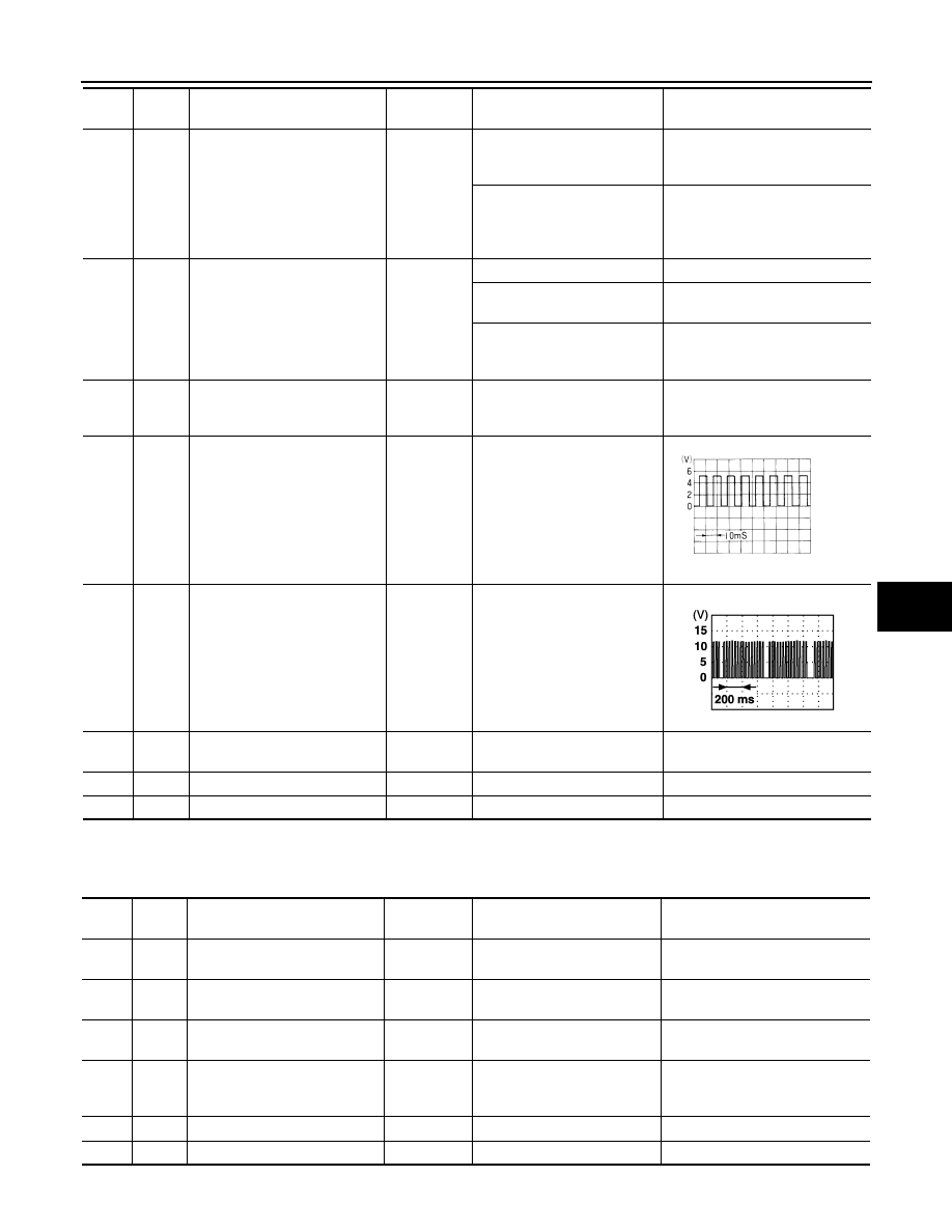
13
PU
Encoder pulse signal
Input
When power window motor
operates.
14
Y
Power window serial link
Input/Output
IGN SW ON or power window
timer operating.
15
W
Encoder power supply
Output
When ignition switch ON or
power window timer operates
10
17
B
Ground
—
—
0
19
W
Battery power supply
Input
—
Battery voltage
Ter-
minal
Wire
color
Item
Signal
Input/Output
Condition
Voltage [V]
(Approx.)
OCC3383D
PIIA2344J
Ter-
minal
Wire
color
Item
Signal
Input/Output
Condition
Voltage [V]
(Approx.)
3
SB
Limit switch and encoder
ground
Input
—
0
4
R
Encoder power supply
Output
When ignition switch ON or
power window timer operates
10
8
L
Front passenger side
power window motor UP signal
Output
When power window motor is
UP at operated.
Battery voltage
9
G
Front passenger side
power window motor DOWN
signal
Output
When power window motor is
DOWN at operated.
Battery voltage
10
W
Battery power supply
Input
—
Battery voltage
11
B
Ground
—
—
0
GW-26
< SERVICE INFORMATION >
POWER WINDOW SYSTEM
CONSULT-III Function
INFOID:0000000001327971
ACTIVE TEST
WORK SUPPORT
DATE MONITOR
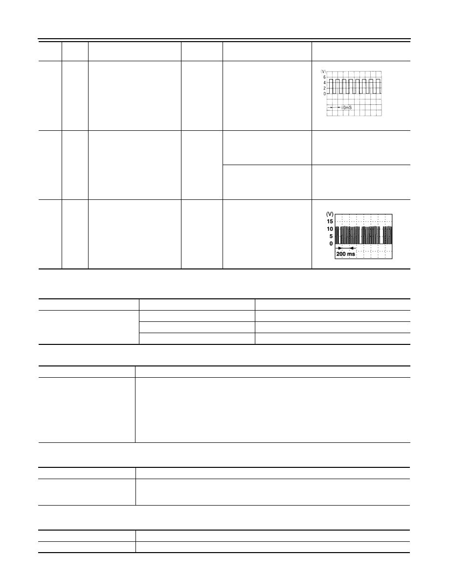
12
PU
Encoder pulse signal
Input
When power window motor
operates.
15
GY
Limit switch signal
Input
Passenger side door window
is between fully-open and just
before fully-closed position
(ON)
0
Passenger side door window
is between just before fully-
closed position and fully-
closed position (OFF)
5
16
Y
Power window serial link
Input/Output
IGN SW ON or power window
timer operating.
Ter-
minal
Wire
color
Item
Signal
Input/Output
Condition
Voltage [V]
(Approx.)
OCC3383D
PIIA2344J
BCM diagnostic test item
Check item diagnostic test mode
Content
RETAINED PWR
Work support
Changes setting of each function.
Data monitor
Displays the input data of BCM in real time.
Active test
Gives a drive signal to a load to check the operation.
Test Item
Description
RETAINED PWR
This test is able to supply RAP signal (power) from BCM (body control module) to power window
system and power sunroof system (if equipped). Those systems can be operated when turning on
“RETAINED PWR” on CONSULT-III screen even if the ignition switch is turned OFF.
NOTE:
During this test, CONSULT-III can be operated with ignition switch in “OFF” position. “RETAINED
PWR” should be turned “ON” or “OFF” on CONSULT-III screen when ignition switch is ON. Then
turn ignition switch OFF to check retained power operation. CONSULT-III might be stuck if “RE-
TAINED PWR” is turned to “ON” or “OFF” on CONSULT-III screen when ignition switch is OFF.
Work item
Description
RETAINED PWR
Rap signal’s power supply period can be changed by mode setting. Selects rap signal’s power sup-
ply period between three steps
• MODE1 (45 sec.) / MODE2 (OFF) / MODE 3 (2 min.).
Work item
Description
IGN ON SW
Indicates (ON / OFF) condition of ignition switch

POWER WINDOW SYSTEM
GW-27
< SERVICE INFORMATION >
C
D
E
F
G
H
J
K
L
M
A
B
GW
N
O
P
Work Flow
INFOID:0000000001327972
1.
Check the symptom and customer's requests.
2.
Understand the outline of system. Refer to
3.
According to the trouble diagnosis chart, repair or replace the cause of the malfunction.
Refer to
GW-27, "Trouble Diagnosis Symptom Chart"
4.
Does power window system operate normally? Yes, GO TO 5, If No, GO TO 3.
5.
INSPECTION END
Trouble Diagnosis Symptom Chart
INFOID:0000000001327973
Make sure other systems using the signal of the following systems operate normally.
DOOR SW–DR
Indicates (ON / OFF) condition of front door switch driver side
DOOR SW–AS
Indicates (ON / OFF) condition of front door switch passenger side
Symptom
Repair order
Refer to page
None of the power windows can be operated using any switch.
1. Check BCM power supply and ground circuit
2. Check power window main switch power
supply and ground circuit
3. Check power window serial link
Driver side power window alone does not operated.
1. Check front power window motor (driver side)
circuit
2. Replace power window main switch
—
Front passenger side power window alone does not operated.
1. Check front power window switch (passenger
side) power and ground circuit
2. Check power window serial link
3. Check front power window motor (passenger
side) circuit
4. Replace BCM
Rear LH side power window alone does not operated
Check rear power window motor (LH) circuit
Rear RH side power window alone does not operated
Check rear power window motor (RH) circuit
Anti-pinch system does not operate normally (driver side)
1. Door window sliding part malfunction
• A foreign material adheres to window glass or
glass run rubber.
• Glass run rubber wear or deformation.
• Sash is tilted too much, or no enough.
—
2. Limit switch adjusting
3. Check limit switch circuit (driver side)
4. Check encoder circuit (driver side)
Anti-pinch system does not operate normally (passenger side)
1. Door window sliding part malfunction
• A foreign material adheres to window glass or
glass run rubber.
• Glass run rubber wear or deformation.
• Sash is tilted too much, or no enough.
—
2. Limit switch adjusting
3. Check limit switch circuit (passenger side)
4. Check encoder circuit (passenger side)
Power window retained power operation does not operate properly
1. Check the retained power operation mode
setting.
2. Check door switch
3. Replace BCM.
Does not operate by key cylinder switch
1. Check door key cylinder switch
2. Replace power window main switch
—
Нет комментариевНе стесняйтесь поделиться с нами вашим ценным мнением.
Текст