Infiniti FX35 / FX45. Manual — part 857

HARNESS
PG-61
< SERVICE INFORMATION >
C
D
E
F
G
H
I
J
L
M
A
B
PG
N
O
P
Code
Section
Wiring Diagram Name
A/C
ATC
Air Conditioner
AF1B1
EC
Air Fuel Ratio Sensor 1 Bank 1
AF1B2
EC
Air Fuel Ratio Sensor 1 Bank 2
AF1HB1
EC
Air Fuel Ratio Sensor 1 Heater Bank 1
AF1HB2
EC
Air Fuel Ratio Sensor 1 Heater Bank 2
APPS1
EC
Accelerator Pedal Position Sensor
APPS2
EC
Accelerator Pedal Position Sensor
APPS3
EC
Accelerator Pedal Position Sensor
ASC/BS
EC
Automatic Speed Control Device (ASCD) Brake Switch
ASC/SW
EC
Automatic Speed Control Device (ASCD) Steering Switch
ASCBOF
EC
Automatic Speed Control Device (ASCD) Brake Switch
ASCIND
EC
Automatic Speed Control Device (ASCD) Indicator
AT/IND
DI
A/T Indicator Lamp
AUDIO
AV
Audio
AUT/DP
SE
Automatic Drive Positioner
AUTO/L
LT
Automatic Light System
AWD
TF
AWD Control System
B/CLOS
BL
Back Door Closure System
BACK/L
LT
Back-Up Lamp
BRK/SW
EC
Brake Switch
CAN
AT
CAN Communication Line
CAN
EC
CAN Communication Line
CAN
LAN
CAN System
CHARGE
SC
Charging System
CHIME
DI
Warning Chime
CLOCK
DI
Clock
COMBSW
LT
Combination Switch
COMM
AV
Audio Visual Communication Line
COMPAS
DI
Compass
COOL/F
EC
Cooling Fan Control
D/LOCK
BL
Power Door Lock
DEF
GW
Rear Window Defogger
DTRL
LT
Headlamp - With Daytime Light System
ECM/PW
EC
ECM Power Supply for Back-Up
ECTS
EC
Engine Coolant Temperature Sensor
ETC1
EC
Electric Throttle Control Function
ETC2
EC
Electric Throttle Control Motor Relay
ETC3
EC
Electric Throttle Control Motor
F/FOG
LT
Front Fog Lamp
F/PUMP
EC
Fuel Pump
FTS
AT
A/T Fluid Temperature Sensor Circuit
FTTS
EC
Fuel Tank Temperature Sensor
FUELB1
EC
Fuel Injection System Function (Bank 1)
FUELB2
EC
Fuel Injection System Function (Bank 2)

PG-62
< SERVICE INFORMATION >
HARNESS
H/AIM
LT
Headlamp Aiming Control System
H/LAMP
LT
Headlamp
H/PHON
AV
Hands Free Telephone
HORN
WW
Horn
HSEAT
SE
Heated Seat
I/KEY
BL
Intelligent Key System
I/MIRR
GW
Inside Mirror (Auto Anti-Dazzling Mirror)
IATS
EC
Intake Air Temperature Sensor
ICC
ACS
Intelligent Cruise Control System
ICC/BS
EC
ICC Brake Switch
ICC/SW
EC
ICC Steering Switch
ICCBOF
EC
ICC Brake Switch
IGNSYS
EC
Ignition System
ILL
LT
Illumination
INF/D
AV
Vehicle Information and Integrated Switch System
INJECT
EC
Injector
IVCB1
EC
Intake Valve Timing Control Solenoid Valve Bank 1
IVCB2
EC
Intake Valve Timing Control Solenoid Valve Bank 2
IVCSB1
EC
Intake Valve Timing Control Position Sensor Bank 1
IVCSB2
EC
Intake Valve Timing Control Position Sensor Bank 2
IVTB1
EC
Intake Valve Timing Control System (Bank 1)
IVTB2
EC
Intake Valve Timing Control System (Bank 2)
KEYLES
BL
Remote Keyless Entry System
KS
EC
Knock Sensor
LDW
DI
Lane Departure Warning System
M/ANT
AV
Manual Antenna
MAFS
EC
Mass Air Flow Sensor
MAIN
AT
Main Power Supply and Ground Circuit
MAIN
EC
Main Power Supply and Ground Circuit
MES
AV
Mobile Entertainment System
METER
DI
Speedometer, Tachometer, Temp. and Fuel Gauges
MIL/DL
EC
MIL & Data Link Connector
MIRROR
GW
Power Door Mirror
MMSW
AT
Manual Mode Switch
NATS
BL
Nissan Anti-Theft System
NAVI
AV
Navigation System
NONDTC
AT
Non-Detective Items
O2H2B1
EC
Heated Oxygen Sensor 2 Heater Bank 1
O2H2B2
EC
Heated Oxygen Sensor 2 Heater Bank 2
O2S2B1
EC
Heated Oxygen Sensor 2 Bank 1
O2S2B2
EC
Heated Oxygen Sensor 2 Bank 2
P/SCKT
WW
Power Socket
PGC/V
EC
EVAP Canister Purge Volume Control Solenoid Valve
PHASE
EC
Camshaft Position Sensor (PHASE)
Code
Section
Wiring Diagram Name

HARNESS
PG-63
< SERVICE INFORMATION >
C
D
E
F
G
H
I
J
L
M
A
B
PG
N
O
P
PHSB1
EC
Camshaft Position Sensor (PHASE) (Bank 1)
PHSB2
EC
Camshaft Position Sensor (PHASE) (Bank 2)
PNP/SW
AT
Park/Neutral Position Switch
PNP/SW
EC
Park/Neutral Position Switch
POS
EC
Crankshaft Position Sensor (CKPS) (POS)
POWER
PG
Power Supply Routing
PRE/SE
EC
EVAP Control System Pressure Sensor
PS/SEN
EC
Power Steering Pressure Sensor
R/VIEW
DI
Rear View Camera Control System
ROOM/L
LT
Interior Room Lamp
RP/SEN
EC
Refrigerant Pressure Sensor
SEAT
SE
Power Seat
SEN/PW
EC
Sensor Power Supply
SHIFT
AT
A/T Shift Lock System
SNOWSW
EC
Snow Mode Switch
SROOF
RF
Sunroof
SRS
SRS
Supplemental Restraint System
START
SC
Starting System
STOP/L
LT
Stop Lamp
STSIG
AT
Start Signal Circuit
T/WARN
WT
Low Tire Pressure Warning System
TAIL/L
LT
Parking, License and Tail Lamps
TPS1
EC
Throttle Position Sensor (Sensor 1)
TPS2
EC
Throttle Position Sensor (Sensor 2)
TPS3
EC
Throttle Position Sensor
TRNSCV
BL
Homelink Universal Transceiver
TURN
LT
Turn Signal and Hazard Warning Lamp
VDC
BRC
Vehicle Dynamics Control System
VEHSEC
BL
Vehicle Security System
VENT/V
EC
EVAP Canister Vent Control Valve
VIAS
EC
Variable Induction Air Control System
VIAS/V
EC
VIAS Control Solenoid Valve
VSSA/T
AT
Vehicle Speed Sensor A/T (Revolution Sensor)
WARN
DI
Warning Lamps
WINDOW
GW
Power Window
WIP/R
WW
Rear Wiper and Washer
WIPER
WW
Front Wiper and Washer
Code
Section
Wiring Diagram Name
PG-64
< SERVICE INFORMATION >
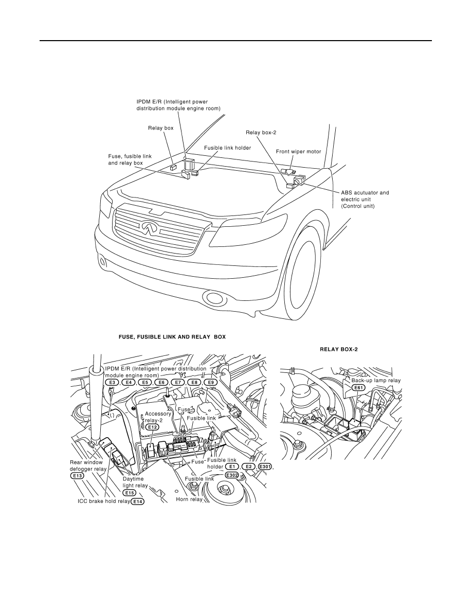
ELECTRICAL UNITS LOCATION
ELECTRICAL UNITS LOCATION
Electrical Units Location
INFOID:0000000001328884
ENGINE COMPARTMENT
CKIM0646E
Нет комментариевНе стесняйтесь поделиться с нами вашим ценным мнением.
Текст