Infiniti FX35 / FX45. Manual — part 531
DTC P0182, P0183 FTT SENSOR
EC-885
< SERVICE INFORMATION >
[VK45DE]
C
D
E
F
G
H
I
J
K
L
M
A
EC
N
P
O
DTC P0182, P0183 FTT SENSOR
Component Description
INFOID:0000000001326713
The fuel tank temperature sensor is used to detect the fuel tempera-
ture inside the fuel tank. The sensor modifies a voltage signal from
the ECM. The modified signal returns to the ECM as the fuel temper-
ature input. The sensor uses a thermistor which is sensitive to the
change in temperature. The electrical resistance of the thermistor
decreases as temperature increases.
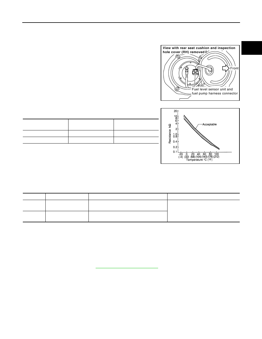
<Reference data>
*: These data are reference values and are measured between ECM terminal 107
(Fuel tank temperature sensor) and ground.
CAUTION:
Do not use ECM ground terminals when measuring input/output
voltage. Doing so may result in damage to the ECM's transistor.
Use a ground other than ECM terminals, such as the ground.
On Board Diagnosis Logic
INFOID:0000000001326714
DTC Confirmation Procedure
INFOID:0000000001326715
NOTE:
If DTC Confirmation Procedure has been previously conducted, always turn ignition switch OFF and wait at
least 10 seconds before conducting the next test.
1.
Turn ignition switch ON and wait at least 5 seconds.
2.
Check 1st trip DTC.
3.
If 1st trip DTC is detected, go to
PBIB1507E
Fluid temperature
°
C (
°
F)
Voltage*
V
Resistance
k
Ω
20 (68)
3.5
2.3 - 2.7
50 (122)
2.2
0.79 - 0.90
SEF012P
DTC No.
Trouble diagnosis name
DTC detecting condition
Possible cause
P0182
0182
Fuel tank temperature
sensor circuit low input
An excessively low voltage from the sensor is
sent to ECM.
• Harness or connectors
(The sensor circuit is open or shorted.)
• Fuel tank temperature sensor
P0183
0183
Fuel tank temperature
sensor circuit high input
An excessively high voltage from the sensor is
sent to ECM.
EC-886
< SERVICE INFORMATION >
[VK45DE]
DTC P0182, P0183 FTT SENSOR
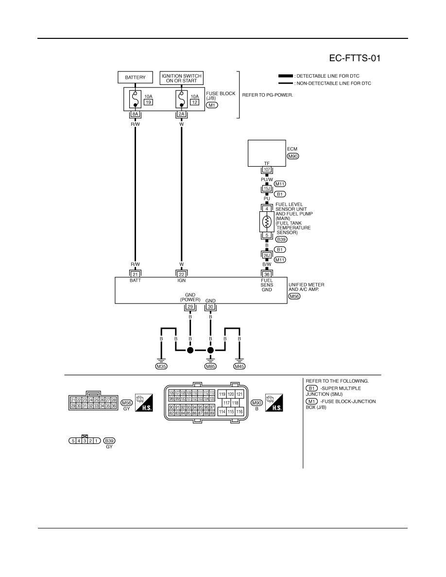
Wiring Diagram
INFOID:0000000001326716
Diagnosis Procedure
INFOID:0000000001326717
1.
CHECK GROUND CONNECTIONS
1.
Turn ignition switch OFF.
2.
Loosen and retighten three ground screws on the body.
TBWM1334E
DTC P0182, P0183 FTT SENSOR
EC-887
< SERVICE INFORMATION >
[VK45DE]
C
D
E
F
G
H
I
J
K
L
M
A
EC
N
P
O
OK or NG
OK
>> GO TO 2.
NG
>> Repair or replace ground connections.
2.
CHECK DTC WITH “UNIFIED METER AND A/C AMP.”
DI-27, "CONSULT-III Function (METER/M&A)"
OK or NG
OK
>> GO TO 3.
NG
>> Go to
DI-19, "Fuel Level Sensor Signal Inspection"
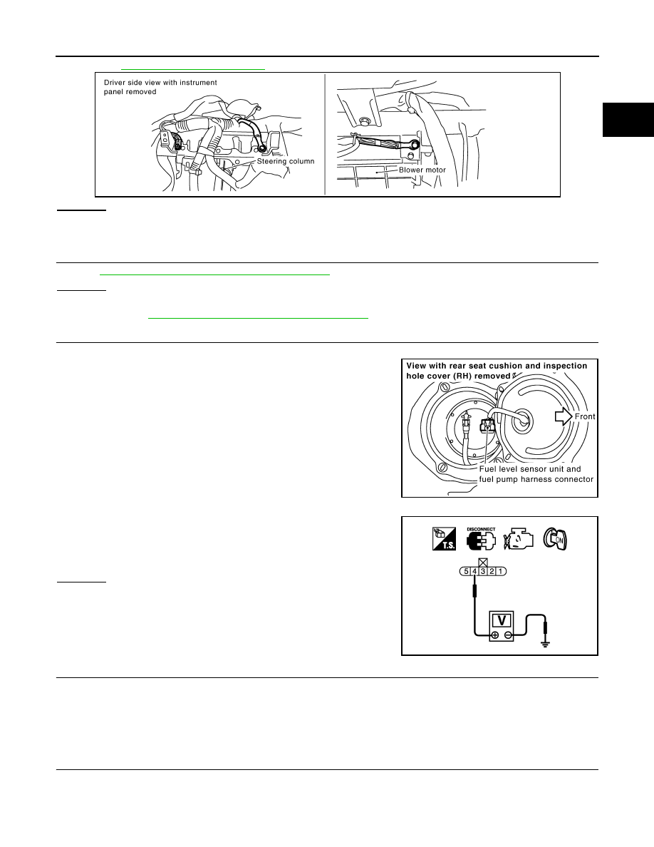
3.
CHECK FUEL TANK TEMPERATURE SENSOR POWER SUPPLY CIRCUIT
1.
Turn ignition switch OFF.
2.
Disconnect “fuel level sensor unit and fuel pump” harness con-
nector.
3.
Turn ignition switch ON.
4.
Check voltage between “fuel level sensor unit and fuel pump”
terminal 4 and ground with CONSULT-III or tester.
OK or NG
OK
>> GO TO 5.
NG
>> GO TO 4.
4.
DETECT MALFUNCTIONING PART
Check the following.
• Harness connectors B1, M11
• Harness for open or short between ECM and “fuel level sensor unit and fuel pump”
>> Repair open circuit or short to ground or short to power in harness or connector.
5.
CHECK FUEL TANK TEMPERATURE SENSOR GROUND CIRCUIT FOR OPEN AND SHORT
1.
Turn ignition switch OFF.
2.
Disconnect “unified meter and A/C amp.” harness connector.
PBIB2195E
PBIB1507E
Voltage: Approximately 5V
PBIB0932E
EC-888
< SERVICE INFORMATION >
[VK45DE]
DTC P0182, P0183 FTT SENSOR
3.
Check harness continuity between “fuel level sensor unit and fuel pump” terminal 5 and “unified meter and
A/C amp.” terminal 36. Refer to Wiring Diagram.
4.
Also check harness for short to ground and short to power.
OK or NG
OK
>> GO TO 7.
NG
>> GO TO 6.
6.
DETECT MALFUNCTIONING PART
Check the following.
• Harness connectors B1, M11
• Harness for open or short between “fuel level sensor unit and fuel pump” and “unified meter and A/C amp.”
>> Repair open circuit or short to ground or short to power in harness or connector.
7.
CHECK FUEL TANK TEMPERATURE SENSOR
EC-884, "Component Inspection"
OK or NG
OK
>> GO TO 8.
NG
>> Replace “fuel level sensor unit and fuel pump”.
8.
CHECK INTERMITTENT INCIDENT
>> INSPECTION END
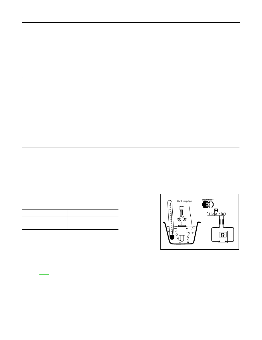
Component Inspection
INFOID:0000000001326718
FUEL TANK TEMPERATURE SENSOR
1.
Remove fuel level sensor unit.
2.
Check resistance between “fuel level sensor unit and fuel pump”
terminals 4 and 5 by heating with hot water.
Removal and Installation
INFOID:0000000001326719
FUEL TANK TEMPERATURE SENSOR
Continuity should exist.
Temperature
°
C (
°
F)
Resistance k
Ω
20 (68)
2.3 - 2.7
50 (122)
0.79 - 0.90
PBIB0931E
Нет комментариевНе стесняйтесь поделиться с нами вашим ценным мнением.
Текст