Infiniti FX35 / FX45. Manual — part 324
ON BOARD DIAGNOSTIC (OBD) SYSTEM
EC-57
< SERVICE INFORMATION >
[VQ35DE]
C
D
E
F
G
H
I
J
K
L
M
A
EC
N
P
O
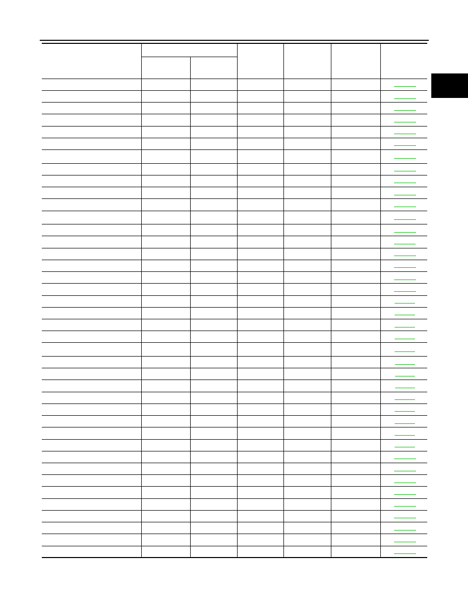
VENT CONTROL VALVE
P0447
0447
—
2
×
VENT CONTROL VALVE
P0448
0448
—
2
×
EVAP SYS PRES SEN
P0451
0451
—
2
×
EVAP SYS PRES SEN
P0452
0452
—
2
×
EVAP SYS PRES SEN
P0453
0453
—
2
×
EVAP GROSS LEAK
P0455
0455
—
2
×
EVAP VERY SML LEAK
P0456
0456
×
*
4
2
×
FUEL LEV SEN SLOSH
P0460
0460
—
2
×
FUEL LEVEL SENSOR
P0461
0461
—
2
×
FUEL LEVL SEN/CIRC
P0462
0462
—
2
×
FUEL LEVL SEN/CIRC
P0463
0463
—
2
×
VEH SPEED SEN/CIRC*
6
P0500
0500
—
2
×
ISC SYSTEM
P0506
0506
—
2
×
ISC SYSTEM
P0507
0507
—
2
×
PW ST P SEN/CIRC
P0550
0550
—
2
—
ECM BACK UP/CIRCUIT
P0603
0603
—
2
×
ECM
P0605
0605
—
1 or 2
×
or —
SENSOR POWER/CIRC
P0643
0643
—
1
×
TCM
P0700
0700
—
1
×
PNP SW/CIRC
P0705
0705
—
2
×
ATF TEMP SEN/CIRC
P0710
0710
—
2
×
TURBINE SENSOR
P0717
0717
—
2
×
VEH SPD SEN/CIR AT*
6
P0720
0720
—
2
×
A/T 1ST GR FNCTN
P0731
0731
—
2
×
A/T 2ND GR FNCTN
P0732
0732
—
2
×
A/T 3RD GR FNCTN
P0733
0733
—
2
×
A/T 4TH GR FNCTN
P0734
0734
—
2
×
A/T 5TH GR FNCTN
P0735
0735
—
2
×
TCC SOLENOID/CIRC
P0740
0740
—
2
×
A/T TCC S/V FNCTN
P0744
0744
—
2
×
L/PRESS SOL/CIRC
P0745
0745
—
2
×
P-N POS SW/CIRCUIT
P0850
0850
—
2
×
CLOSED LOOP-B1
P1148
1148
—
1
×
CLOSED LOOP-B2
P1168
1168
—
1
×
TCS C/U FUNCTN
P1211
1211
—
2
—
TCS/CIRC
P1212
1212
—
2
—
ENG OVER TEMP
P1217
1217
—
1
×
CTP LEARNING-B1
P1225
1225
—
2
—
CTP LEARNING-B1
P1226
1226
—
2
—
COLD START CONTROL
P1421
1421
—
2
×
Items
(CONSULT-III screen terms)
DTC*
1
SRT code
Trip
MIL
Reference
page
CONSULT-III
GST*
2
ECM*
3
EC-58
< SERVICE INFORMATION >
[VQ35DE]
ON BOARD DIAGNOSTIC (OBD) SYSTEM
*1: 1st trip DTC No. is the same as DTC No.
*2: This number is prescribed by SAE J2012.
*3: In Diagnostic Test Mode II (Self-diagnostic results), this number is controlled by NISSAN.
*4: SRT code will not be set if the self-diagnostic result is NG.
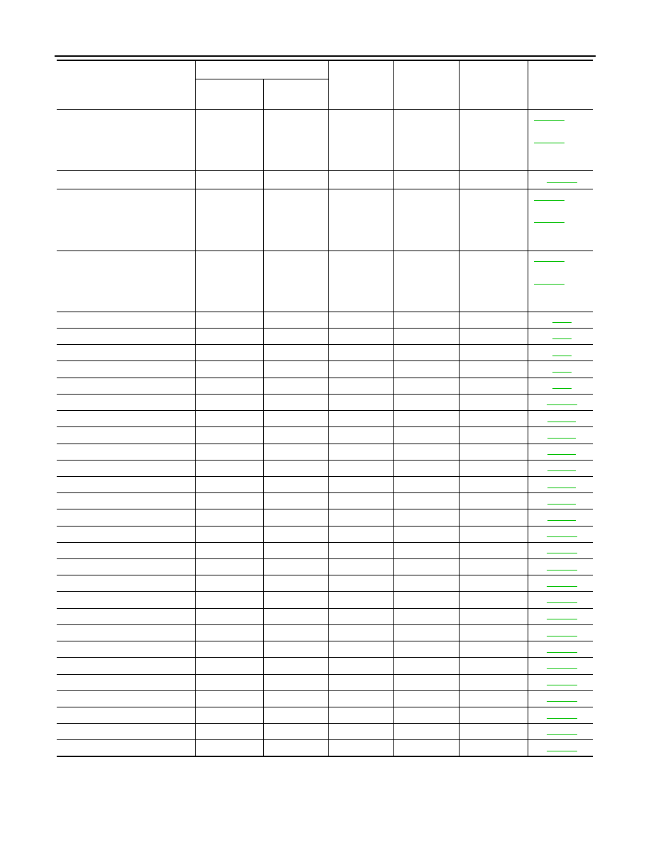
ASCD SW
P1564
1564
—
1
—
els with ICC)
els with AS-
CD)
ICC COMMAND VALUE*
7
P1568
1568
—
1
—
ASCD BRAKE SW
P1572
1572
—
1
—
els with ICC)
els with AS-
CD)
ASCD VHL SPD SEN
P1574
1574
—
1
—
els with ICC)
els with AS-
CD)
LOCK MODE
P1610
1610
—
2
—
ID DISCARD IMM-ECM
P1611
1611
—
2
—
CHAIN OF ECM-IMMU
P1612
1612
—
2
—
CHAIN OF IMMU-KEY
P1614
1614
—
2
—
DIFFERENCE OF KEY
P1615
1615
—
2
—
IN PULLY SPEED
P1715
1715
—
2
—
A/T INTERLOCK
P1730
1730
—
1
×
I/C SOLENOID/CIRC
P1752
1752
—
1
×
FR/B SOLENOID/CIRC
P1757
1757
—
1
×
D/C SOLENOID/CIRC
P1762
1762
—
1
×
HLR/C SOL/CIRC
P1767
1767
—
1
×
LC/B SOLENOID/CIRC
P1772
1772
—
1
×
LC/B SOLENOID FNCT
P1774
1774
—
1
×
BRAKE SW/CIRCUIT
P1805
1805
—
2
—
ETC MOT PWR-B1
P2100
2100
—
1
×
ETC FNCTN/CIRC-B1
P2101
2101
—
1
×
ETC MOT PWR
P2103
2103
—
1
×
ETC MOT-B1
P2118
2118
—
1
×
ETC ACTR-B1
P2119
2119
—
1
×
APP SEN 1/CIRC
P2122
2122
—
1
×
APP SEN 1/CIRC
P2123
2123
—
1
×
APP SEN 2/CIRC
P2127
2127
—
1
×
APP SEN 2/CIRC
P2128
2128
—
1
×
TP SENSOR-B1
P2135
2135
—
1
×
APP SENSOR
P2138
2138
—
1
×
A/F SENSOR1 (B1)
P2A00
2A00
—
2
×
A/F SENSOR1 (B2)
P2A03
2A03
—
2
×
Items
(CONSULT-III screen terms)
DTC*
1
SRT code
Trip
MIL
Reference
page
CONSULT-III
GST*
2
ECM*
3

ON BOARD DIAGNOSTIC (OBD) SYSTEM
EC-59
< SERVICE INFORMATION >
[VQ35DE]
C
D
E
F
G
H
I
J
K
L
M
A
EC
N
P
O
*5: The trouble shooting for this DTC needs CONSULT-III.
*6: When the fail-safe operations for both self-diagnoses occur, the MIL illuminates.
*7: For models with ICC system.
*8: When the ECM is in the mode of displaying SRT status, MIL may flash. For the details, refer to “How to Display SRT Status”.
DTC AND 1ST TRIP DTC
The 1st trip DTC (whose number is the same as the DTC number) is displayed for the latest self-diagnostic
result obtained. If the ECM memory was cleared previously, and the 1st trip DTC did not reoccur, the 1st trip
DTC will not be displayed.
If a malfunction is detected during the 1st trip, the 1st trip DTC is stored in the ECM memory. The MIL will not
light up (two trip detection logic). If the same malfunction is not detected in the 2nd trip (meeting the required
driving pattern), the 1st trip DTC is cleared from the ECM memory. If the same malfunction is detected in the
2nd trip, both the 1st trip DTC and DTC are stored in the ECM memory and the MIL lights up. In other words,
the DTC is stored in the ECM memory and the MIL lights up when the same malfunction occurs in two consec-
utive trips. If a 1st trip DTC is stored and a non-diagnostic operation is performed between the 1st and 2nd
trips, only the 1st trip DTC will continue to be stored. For malfunctions that blink or light up the MIL during the
1st trip, the DTC and 1st trip DTC are stored in the ECM memory.
Procedures for clearing the DTC and the 1st trip DTC from the ECM memory are described in “HOW TO
ERASE EMISSION-RELATED DIAGNOSTIC INFORMATION”.
For malfunctions in which 1st trip DTCs are displayed, refer to “EMISSION-RELATED DIAGNOSTIC INFOR-
MATION ITEMS”. These items are required by legal regulations to continuously monitor the system/compo-
nent. In addition, the items monitored non-continuously are also displayed on CONSULT-III.
1st trip DTC is specified in Service $07 of SAE J1979. 1st trip DTC detection occurs without lighting up the MIL
and therefore does not warn the driver of a malfunction. However, 1st trip DTC detection will not prevent the
vehicle from being tested, for example during Inspection/Maintenance (I/M) tests.
When a 1st trip DTC is detected, check, print out or write down and erase (1st trip) DTC and Freeze Frame
data as specified in Work Flow procedure Step II, refer to
EC-89, "Trouble Diagnosis Introduction"
. Then per-
form DTC Confirmation Procedure or Overall Function Check to try to duplicate the malfunction. If the mal-
function is duplicated, the item requires repair.
How to Read DTC and 1st Trip DTC
DTC and 1st trip DTC can be read by the following methods.
With CONSULT-III
With GST
CONSULT-III or GST (Generic Scan Tool) Examples: P0340, P0850, P1148, etc.
These DTCs are prescribed by SAE J2012.
(CONSULT-III also displays the malfunctioning component or system.)
No Tools
The number of blinks of the MIL in the Diagnostic Test Mode II (Self-Diagnostic Results) indicates the DTC.
Example: 0340, 0850, 1148, etc.
These DTCs are controlled by NISSAN.
• 1st trip DTC No. is the same as DTC No.
• Output of a DTC indicates a malfunction. However, GST or the Diagnostic Test Mode II do not indi-
cate whether the malfunction is still occurring or has occurred in the past and has returned to nor-
mal. CONSULT-III can identify malfunction status as shown below. Therefore, using CONSULT-III (if
available) is recommended.
DTC or 1st trip DTC of a malfunction is displayed in SELF-DIAGNOSTIC RESULTS mode of CONSULT-III.
Time data indicates how many times the vehicle was driven after the last detection of a DTC.
If the DTC is being detected currently, the time data will be [0].
If a 1st trip DTC is stored in the ECM, the time data will be [1t].
FREEZE FRAME DATA AND 1ST TRIP FREEZE FRAME DATA
The ECM records the driving conditions such as fuel system status, calculated load value, engine coolant tem-
perature, short term fuel trim, long term fuel trim, engine speed, vehicle speed, absolute throttle position, base
fuel schedule and intake air temperature at the moment a malfunction is detected.
Data which are stored in the ECM memory, along with the 1st trip DTC, are called 1st trip freeze frame data.
The data, stored together with the DTC data, are called freeze frame data and displayed on CONSULT-III or
GST. The 1st trip freeze frame data can only be displayed on the CONSULT-III screen, not on the GST. For
details, see
EC-117, "CONSULT-III Function (ENGINE)"
Only one set of freeze frame data (either 1st trip freeze frame data or freeze frame data) can be stored in the
ECM. 1st trip freeze frame data is stored in the ECM memory along with the 1st trip DTC. There is no priority
EC-60
< SERVICE INFORMATION >
[VQ35DE]
ON BOARD DIAGNOSTIC (OBD) SYSTEM
for 1st trip freeze frame data and it is updated each time a different 1st trip DTC is detected. However, once
freeze frame data (2nd trip detection/MIL on) is stored in the ECM memory, 1st trip freeze frame data is no
longer stored. Remember, only one set of freeze frame data can be stored in the ECM. The ECM has the fol-
lowing priorities to update the data.
For example, the EGR malfunction (Priority: 2) was detected and the freeze frame data was stored in the 2nd
trip. After that when the misfire (Priority: 1) is detected in another trip, the freeze frame data will be updated
from the EGR malfunction to the misfire. The 1st trip freeze frame data is updated each time a different mal-
function is detected. There is no priority for 1st trip freeze frame data. However, once freeze frame data is
stored in the ECM memory, 1st trip freeze data is no longer stored (because only one freeze frame data or 1st
trip freeze frame data can be stored in the ECM). If freeze frame data is stored in the ECM memory and freeze
frame data with the same priority occurs later, the first (original) freeze frame data remains unchanged in the
ECM memory.
Both 1st trip freeze frame data and freeze frame data (along with the DTCs) are cleared when the ECM mem-
ory is erased. Procedures for clearing the ECM memory are described in “HOW TO ERASE EMISSION-
RELATED DIAGNOSTIC INFORMATION”.
SYSTEM READINESS TEST (SRT) CODE
System Readiness Test (SRT) code is specified in Service $01 of SAE J1979.
As part of an enhanced emissions test for Inspection & Maintenance (I/M), certain states require the status of
SRT be used to indicate whether the ECM has completed self-diagnosis of major emission systems and com-
ponents. Completion must be verified in order for the emissions inspection to proceed.
If a vehicle is rejected for a State emissions inspection due to one or more SRT items indicating “INCMP”, use
the information in this Service Manual to set the SRT to “CMPLT”.
In most cases the ECM will automatically complete its self-diagnosis cycle during normal usage, and the SRT
status will indicate “CMPLT” for each application system. Once set as “CMPLT”, the SRT status remains
“CMPLT” until the self-diagnosis memory is erased.
Occasionally, certain portions of the self-diagnostic test may not be completed as a result of the customer's
normal driving pattern; the SRT will indicate “INCMP” for these items.
NOTE:
The SRT will also indicate “INCMP” if the self-diagnosis memory is erased for any reason or if the ECM mem-
ory power supply is interrupted for several hours.
If, during the state emissions inspection, the SRT indicates “CMPLT” for all test items, the inspector will con-
tinue with the emissions test. However, if the SRT indicates “INCMP” for one or more of the SRT items the
vehicle is returned to the customer untested.
NOTE:
If MIL is ON during the state emissions inspection, the vehicle is also returned to the customer untested even
though the SRT indicates “CMPLT” for all test items. Therefore, it is important to check SRT (“CMPLT”) and
DTC (No DTCs) before the inspection.
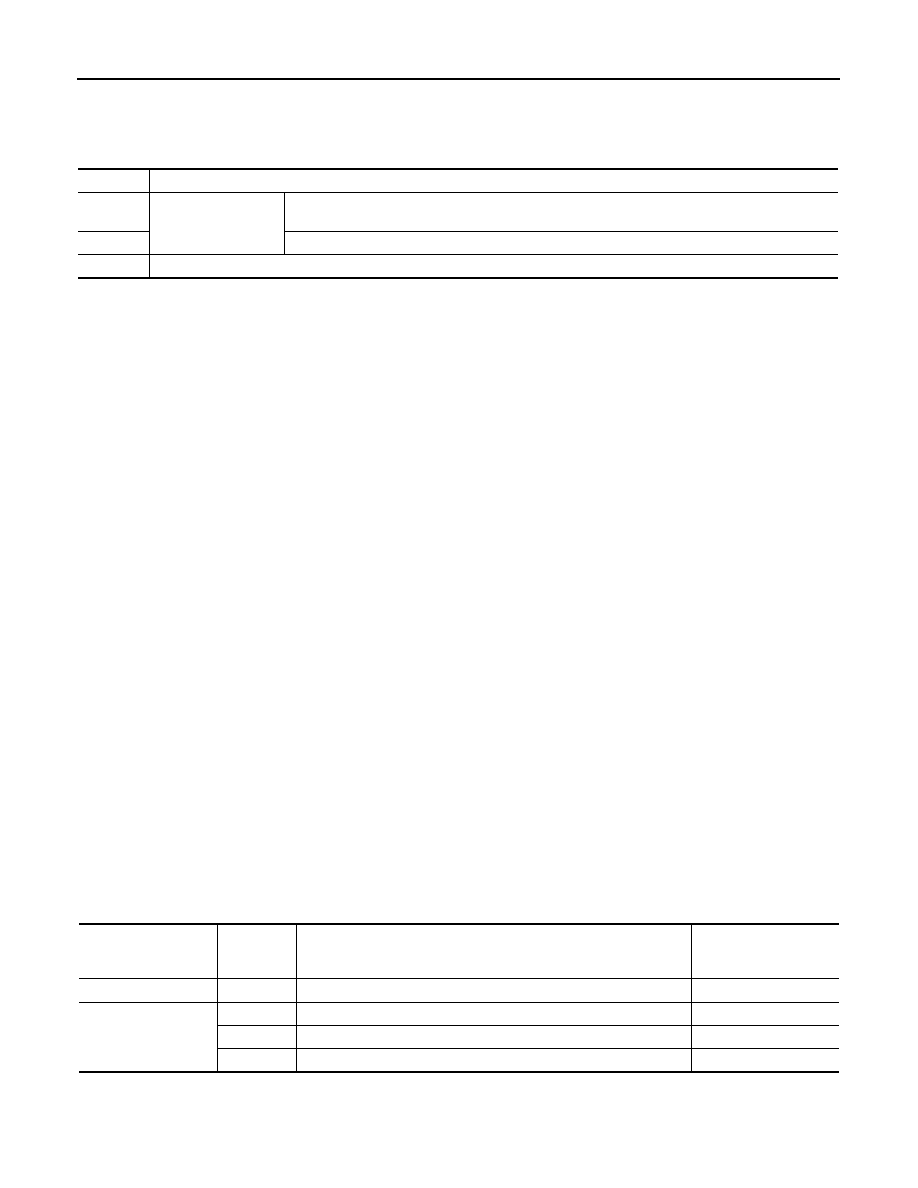
SRT Item
The table below shows required self-diagnostic items to set the SRT to “CMPLT”.
Priority
Items
1
Freeze frame data
Misfire — DTC: P0300 - P0306
Fuel Injection System Function — DTC: P0171, P0172, P0174, P0175
2
Except the above items (Includes A/T related items)
3
1st trip freeze frame data
SRT item
(CONSULT-III indica-
tion)
Perfor-
mance Pri-
ority*
Required self-diagnostic items to set the SRT to “CMPLT”
Corresponding DTC No.
CATALYST
2
Three way catalyst function
P0420, P0430
EVAP SYSTEM
1
EVAP control system
P0442
2
EVAP control system
P0456
2
EVAP control system purge flow monitoring
P0441
Нет комментариевНе стесняйтесь поделиться с нами вашим ценным мнением.
Текст