Infiniti FX35 / FX45. Manual — part 754
IP-12
< SERVICE INFORMATION >
INSTRUMENT PANEL ASSEMBLY
[]: Number indicates step in removal procedures.
REMOVAL
(A) Front Kicking Plate (RH/LH)
Remove front kicking plate (RH/LH). Refer to
(B) Dash Side Finisher (RH/LH)
1.
Remove plastics nut.
2.
Remove dash side finisher (RH/LH). Refer to
.
(C) Front Pillar Garnish (RH/LH)
Pull to inside of vehicle, disengage metal clips and remove front pillar garnish. Refer to
.
(D) A/T Select Lever Knob
1.
Pull down knob cover.
2.
Remove lock-pin of select lever knob.
3.
Lift up select lever knob and remove select lever knob.
Refer to
AT-205, "Control Device Removal and Installation"
(E) Instrument Clock Finisher
1.
Remove screw and then pull back to your side of instrument
clock finisher.
2.
Disconnect clips and harness connector, and remove instrument
clock finisher.
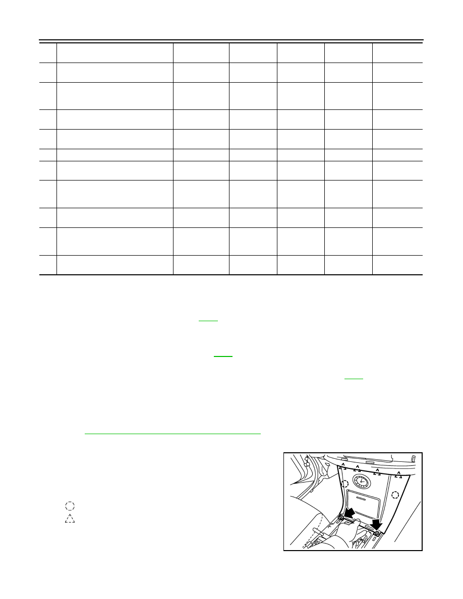
(F) A/T Console Finisher
(O)
Wiper and washer switch
(O) Wiper and
Washer Switch
[15]
[7]
(P)
Lighting and turn signal switch
(P) Lighting and
Turn Signal
Switch
[16]
[8]
(Q)
Steering lock escutcheon
(Q) Steering Lock
Escutcheon
[17]
[9]
(R)
Combination meter assembly
(R) Combination
Meter Assembly
[18]
[10]
(S)
Cluster lid C
(S) Cluster Lid C
[19]
[1]
(T)
Display unit and audio unit
(T) Display Unit
and Audio Unit
[20]
[2]
(U)
Front defroster grille (RH/LH)
(U) Front
Defroster Grille
(RH/LH)
[21]
(V)
Combination meter bracket
(V) Combination
Meter Bracket
[22]
(W)
Side ventilation (RH/LH)
(W) Side
Ventilation
(RH/LH)
[23]
(X)
Instrument panel and pad
(X) Instrument
Panel and Pad
[24]
Parts
Reference
page
Instrument
panel and pad
Combination
meter
Display unit
and audio unit
Center console
: Clip
: Pawl
PIIB8535E
INSTRUMENT PANEL ASSEMBLY
IP-13
< SERVICE INFORMATION >
C
D
E
F
G
H
J
K
L
M
A
B
IP
N
O
P
1.
Insert a remover into side between gaps of A/T console finisher
assembly and remove by lifting A/T console finisher.
2.
Disconnect harness connector.
(G) Instrument Side Panel (RH/LH)
1.
Remove screws with power tool.
2.
Pull to the side, disconnect clip and pawls and remove instru-
ment side panel (RH/LH).
(H) Center Console
1.
Remove screws with power tool.
2.
Remove console sub-harness
3.
After removing, disassemble, each parts.
CAUTION:
When removing console, be careful not to pull the harness.
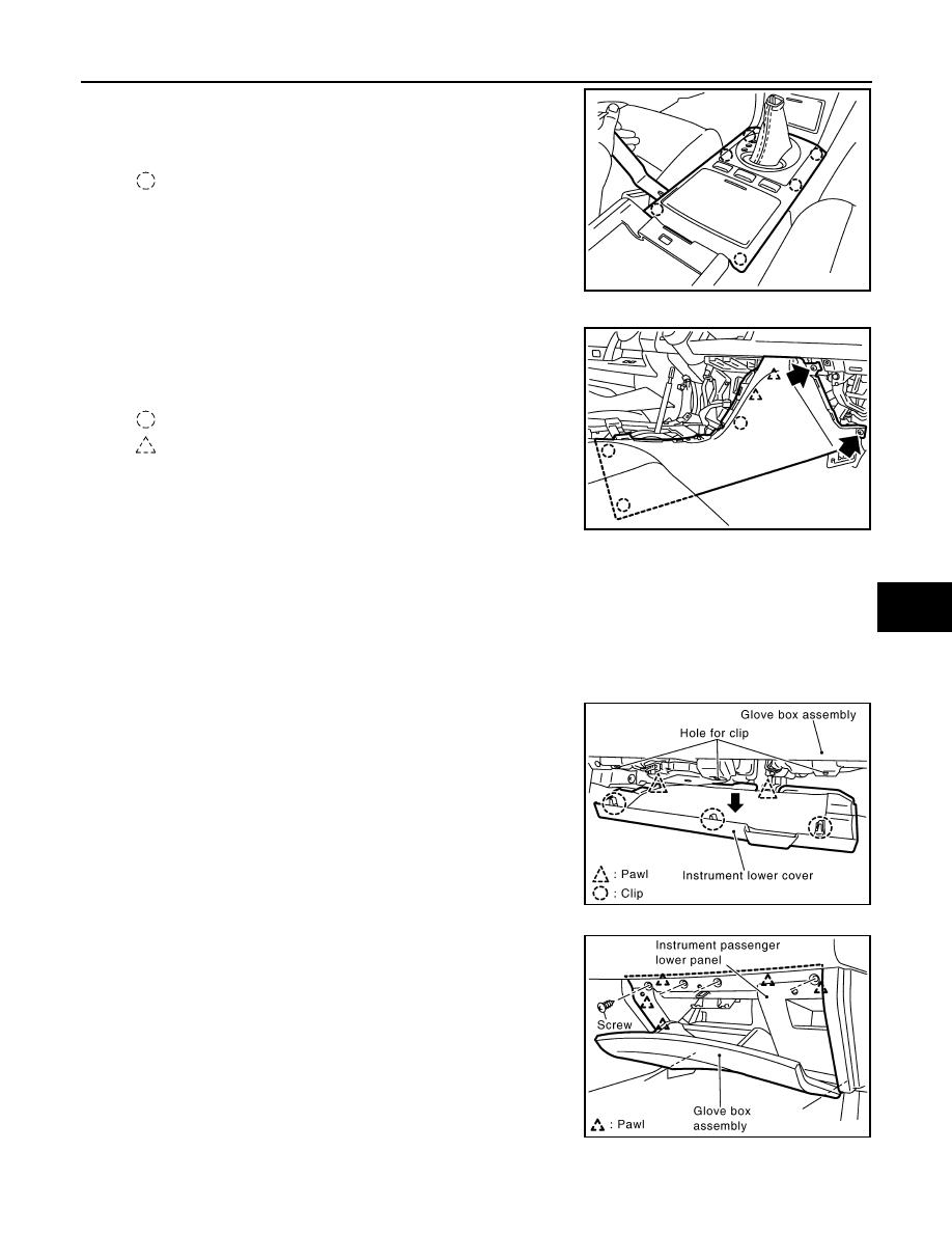
(I) Instrument Lower Cover
1.
Pull down front instrument lower cover, and disconnect clips.
2.
Pull it horizontally, and remove from lower cover pawls.
(J) Instrument Passenger Lower Panel
Remove screws with power tool, and disconnect harness connector,
and remove instrument passenger lower panel.
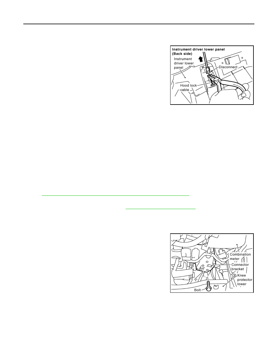
(K) Instrument Driver Lower Panel
1.
Remove bolt and screws with power tool.
: Clip
PIIB8534E
: Clip
: Pawl
PIIB8536E
PIIA5007E
PIIA4995E
IP-14
< SERVICE INFORMATION >
INSTRUMENT PANEL ASSEMBLY
2.
Remove data link connector.
3.
Pull to disengage clip and pawl by removing panel in horizontal direction.
4.
Disconnect in-vehicle sensor and each electrical parts.
5.
Remove the grommet, and remove hood lock cable.
(L) Steering Column Front Lower Cover
1.
Remove screw with power tool.
2.
Disengage the tab, then remove steering column front lower cover.
NOTE:
• Move the steering column telescopic to the rear most position
• Move the steering column tilt to the top position.
(M) Steering Column Lower Cover
1.
Remove screws with power tool.
2.
Disengage the tab, then remove steering column lower cover.
(N) Steering Column Upper Cover
Remove the steering column upper cover.
(O) Wiper and Washer Switch
Remove wiper and washer switch.
Refer to
WW-28, "Removal and Installation of Front Wiper and Washer Switch"
(P) Lighting and Turn Signal Switch
Remove lighting and turn signal switch. Refer to
LT-96, "Removal and Installation"
(Q) Steering Lock Escutcheon
Pull back to your side, and remove steering lock escutcheon.
(R) Combination Meter Assembly
1.
Remove bolts with power tool, and then remove connector
bracket.
PIIA4998E
PIIA5002E
INSTRUMENT PANEL ASSEMBLY
IP-15
< SERVICE INFORMATION >
C
D
E
F
G
H
J
K
L
M
A
B
IP
N
O
P
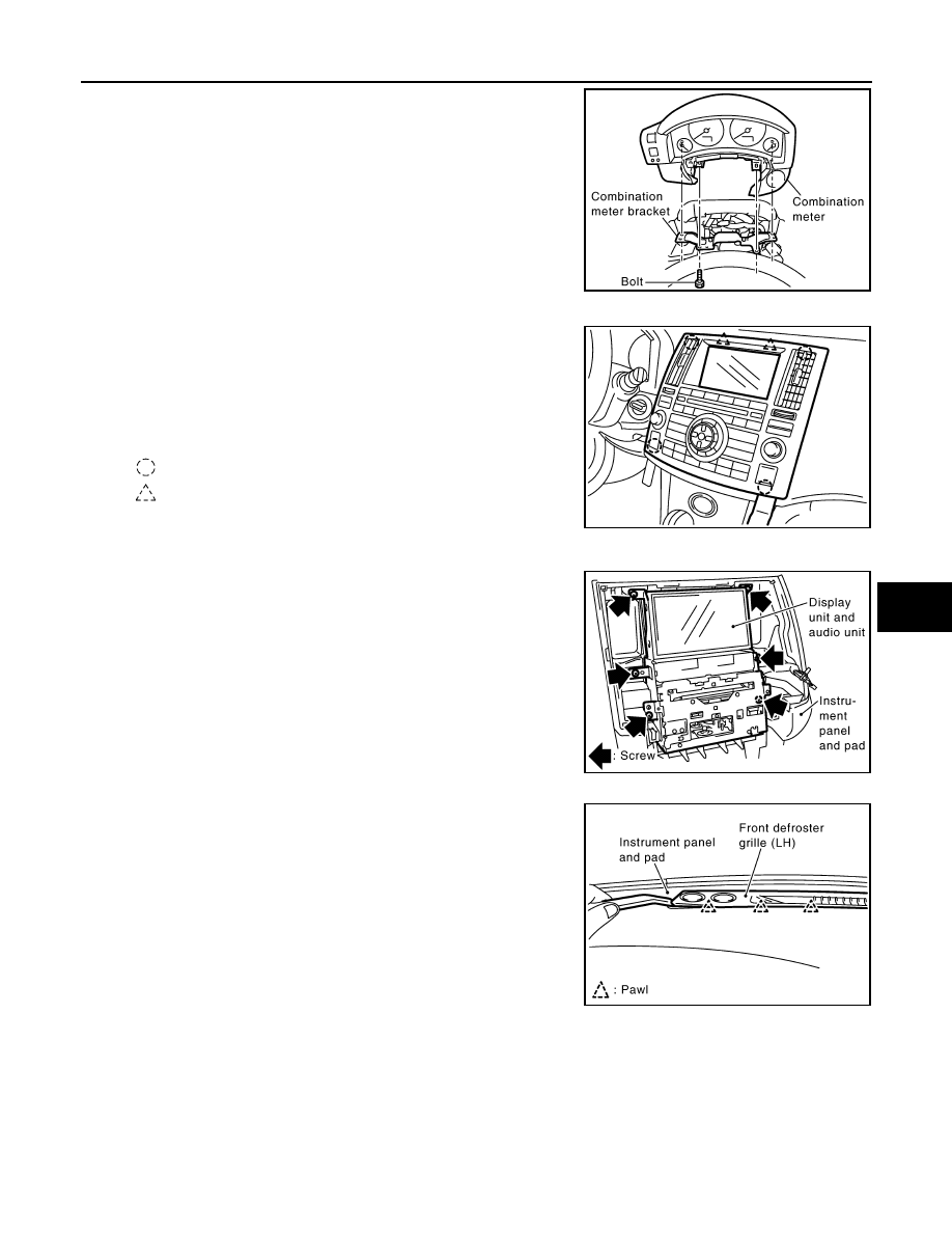
2.
Remove bolts with power tool and then disconnect harness con-
nector.
CAUTION:
To prevent it from damaged by interference with the combina-
tion meter assembly, protect the combination meter assembly
with cloths.
(S) Cluster Lid C
1.
Insert a remover into gap between instrument panel and pad,
pull back to your side, and disconnect metal clips below.
2.
Disconnect harness connectors, and remove cluster lid C.
CAUTION:
Cover surroundings with cloth to avoid scratches or dam-
ages.
(T) Display Unit and Audio Unit
1.
Remove screws with power tool.
2.
Disconnect harness connector, and remove display unit and
audio unit.
CAUTION:
Unit is heavy, so be careful not to pinch your fingers when
working.
(U) Front Defroster Grille (RH/LH)
Insert a remover into gaps between front defroster grille (RH/LH) and
instrument panel and pad, lift front defroster grille up, and remove
front defroster grille (RH/LH).
(V) Combination Meter Bracket
PIIA5003E
: Clip
: Pawl
PIIB8533E
PIIB1335E
PIIA5009E
Нет комментариевНе стесняйтесь поделиться с нами вашим ценным мнением.
Текст