Infiniti FX35 / FX45. Manual — part 599
FUEL PUMP
EC-1157
< SERVICE INFORMATION >
[VK45DE]
C
D
E
F
G
H
I
J
K
L
M
A
EC
N
P
O
Diagnosis Procedure
INFOID:0000000001327060
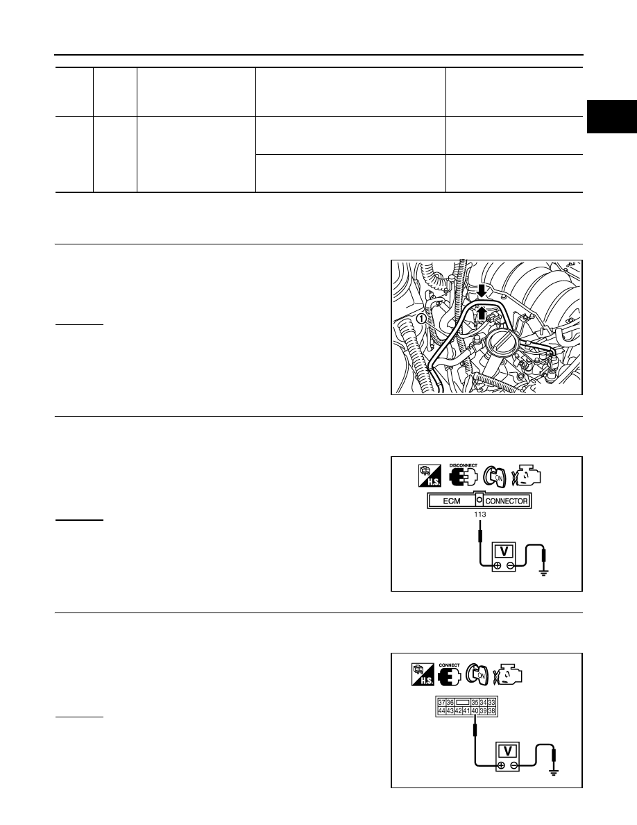
1.
CHECK OVERALL FUNCTION
1.
Turn ignition switch ON.
2.
Pinch fuel feed hose (1) with two fingers.
OK or NG
OK
>> INSPECTION END
NG
>> GO TO 2.
2.
CHECK FUEL PUMP POWER SUPPLY CIRCUIT-I
1.
Turn ignition switch OFF.
2.
Disconnect ECM harness connector.
3.
Turn ignition switch ON.
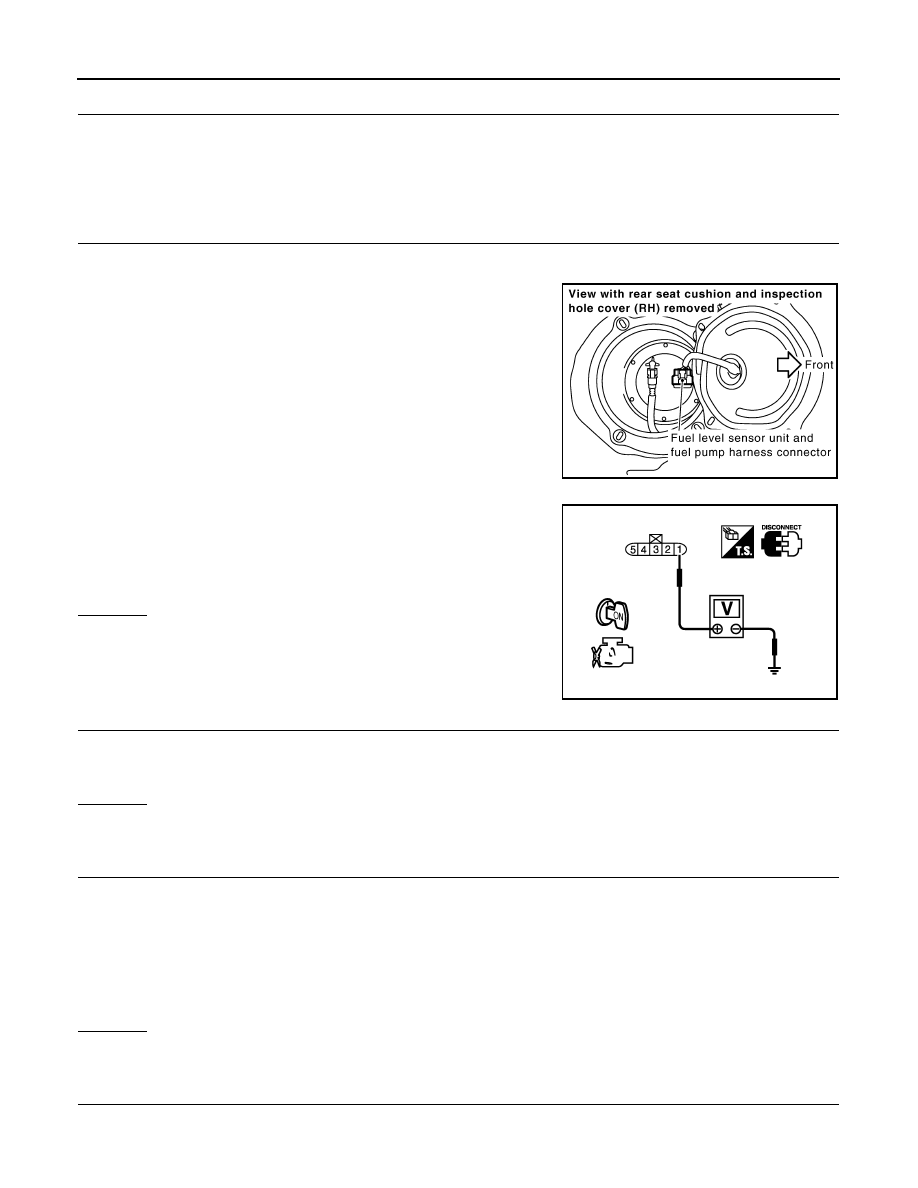
4.
Check voltage between ECM terminal 113 and ground with
CONSULT-III or tester.
OK or NG
OK
>> GO TO 5.
NG
>> GO TO 3.
3.
CHECK FUEL PUMP POWER SUPPLY CIRCUIT-II
1.
Turn ignition switch OFF.
2.
Disconnect IPDM E/R harness connector E8.
3.
Turn ignition switch ON.
4.
Check voltage between IPDM E/R terminal 40 and ground with
CONSULT-III or tester.
OK or NG
OK
>> GO TO 4.
NG
>> GO TO 11.
TER-
MI-
NAL
NO.
WIRE
COLOR
ITEM
CONDITION
DATA (DC Voltage)
113
GY/R
Fuel pump relay
[Ignition switch: ON]
• For 1 second after turning ignition switch ON
[Engine is running]
0 - 1.5V
[Ignition switch: ON]
• More than 1 second after turning ignition
switch ON
BATTERY VOLTAGE
(11 - 14V)
Fuel pressure pulsation should be felt on the fuel feed
hose for 1 second after ignition switch is turned ON.
PBIB3245E
Voltage: Battery voltage
PBIB1187E
Voltage: Battery voltage
PBIB1926E
EC-1158
< SERVICE INFORMATION >
[VK45DE]
FUEL PUMP
4.
DETECT MALFUNCTIONING PART
Check the following.
• Harness connectors E211, M41
• Harness for open or short between IPDM E/R and ECM
>> Repair open circuit or short to ground or short to power in harness or connectors.
5.
CHECK FUEL PUMP POWER SUPPLY CIRCUIT-III
1.
Turn ignition switch OFF.
2.
Reconnect all harness connectors disconnected.
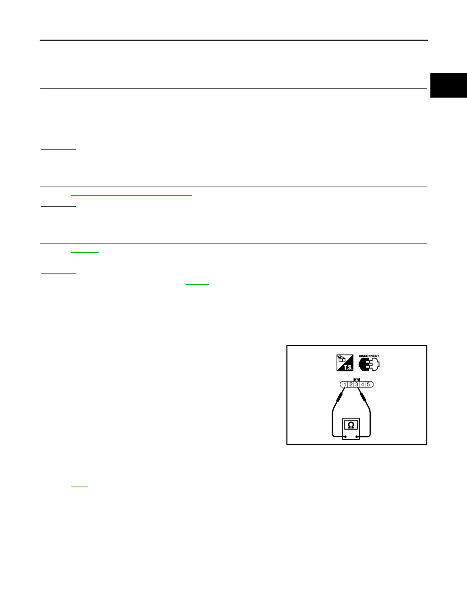
3.
Disconnect “fuel level sensor unit and fuel pump” harness con-
nector.
4.
Turn ignition switch ON.
5.
Check voltage between “fuel level sensor unit and fuel pump”
terminal 1 and ground with CONSULT-III or tester.
OK or NG
OK
>> GO TO 9.
NG
>> GO TO 6.
6.
CHECK 15A FUSE
1.
Turn ignition switch OFF.
2.
Disconnect 15A fuse.
3.
Check 15A fuse.
OK or NG
OK
>> GO TO 7.
NG
>> Replace fuse.
7.
CHECK FUEL PUMP POWER SUPPLY CIRCUIT-IV
1.
Disconnect IPDM E/R harness connector E8.
2.
Check harness continuity between IPDM E/R terminal 39 and “fuel level sensor unit and fuel pump” termi-
nal 1.
Refer to Wiring Diagram.
3.
Also check harness for short to ground and short to power.
OK or NG
OK
>> GO TO 11.
NG
>> GO TO 8.
8.
DETECT MALFUNCTIONING PART
Check the following.
• Harness connectors E206, B6
PBIB1507E
Voltage:
Battery voltage should exist for 1 sec-
ond after ignition switch is turned ON.
PBIB0795E
Continuity should exist.
FUEL PUMP
EC-1159
< SERVICE INFORMATION >
[VK45DE]
C
D
E
F
G
H
I
J
K
L
M
A
EC
N
P
O
• Harness for open or short between IPDM E/R and “fuel level sensor unit and fuel pump”
>> Repair harness or connectors.
9.
CHECK FUEL PUMP GROUND CIRCUIT FOR OPEN AND SHORT
1.
Check harness continuity between “fuel level sensor unit and fuel pump” terminal 3 and ground.
Refer to Wiring Diagram.
2.
Also check harness for short to power.
OK or NG
OK
>> GO TO 10.
NG
>> Repair open circuit or short to power in harness or connectors.
10.
CHECK FUEL PUMP
EC-1159, "Component Inspection"
.
OK or NG
OK
>> GO TO 11.
NG
>> Replace fuel pump.
11.
CHECK INTERMITTENT INCIDENT
OK or NG
OK
>> Replace IPDM E/R. Refer to
.
NG
>> Repair or replace harness or connectors.
Component Inspection
INFOID:0000000001327061
FUEL PUMP
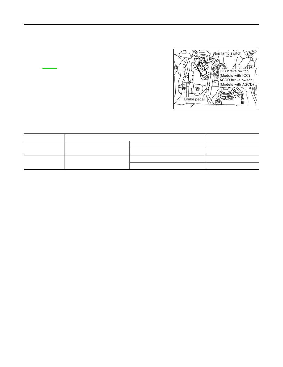
1.
Disconnect “fuel level sensor unit and fuel pump” harness connector.
2.
Check resistance between “fuel level sensor unit and fuel pump”
terminals 1 and 3.
Removal and Installation
INFOID:0000000001327062
FUEL PUMP
Continuity should exist.
Resistance: 0.2 - 5.0
Ω
[at 25
°
C (77
°
F)]
SEC918C
EC-1160
< SERVICE INFORMATION >
[VK45DE]
ICC BRAKE SWITCH
ICC BRAKE SWITCH
Component Description
INFOID:0000000001327063
When depress on the brake pedal, ICC brake switch is turned OFF
and stop lamp switch is turned ON. ECM detects the state of the
brake pedal by this input of two kinds (ON/OFF signal)
Refer to
CONSULT-III Reference Value in Data Monitor Mode
INFOID:0000000001327064
Specification data are reference values.
PBIB2558E
MONITOR ITEM
CONDITION
SPECIFICATION
BRAKE SW1
(ICC brake switch)
• Ignition switch: ON
Brake pedal: Fully released
ON
Brake pedal: Slightly depressed
OFF
BRAKE SW2
(Stop lamp switch)
• Ignition switch: ON
Brake pedal: Fully released
OFF
Brake pedal: Slightly depressed
ON
Нет комментариевНе стесняйтесь поделиться с нами вашим ценным мнением.
Текст