Infiniti FX35 / FX45. Manual — part 231
IVIS (INFINITI VEHICLE IMMOBILIZER SYSTEM-NATS)
BL-191
< SERVICE INFORMATION >
C
D
E
F
G
H
J
K
L
M
A
B
BL
N
O
P
Terminal and Reference Value for Steering Lock Unit/with Intelligent Key System
INFOID:0000000001327927
Terminal and Reference Value for Intelligent Key Unit/with Intelligent Key System
INFOID:0000000001327928
Ter-
minal
Wire
color
Signal Designation
Signal
Input/
output
Measuring condition
Voltage (V)
(Approx.)
Ignition knob
position
Operation or conditions
1
L/R
Power source (Fuse)
Input
LOCK
—
Battery voltage
2
R/W
Steering lock unit power
supply
Input
LOCK
—
5
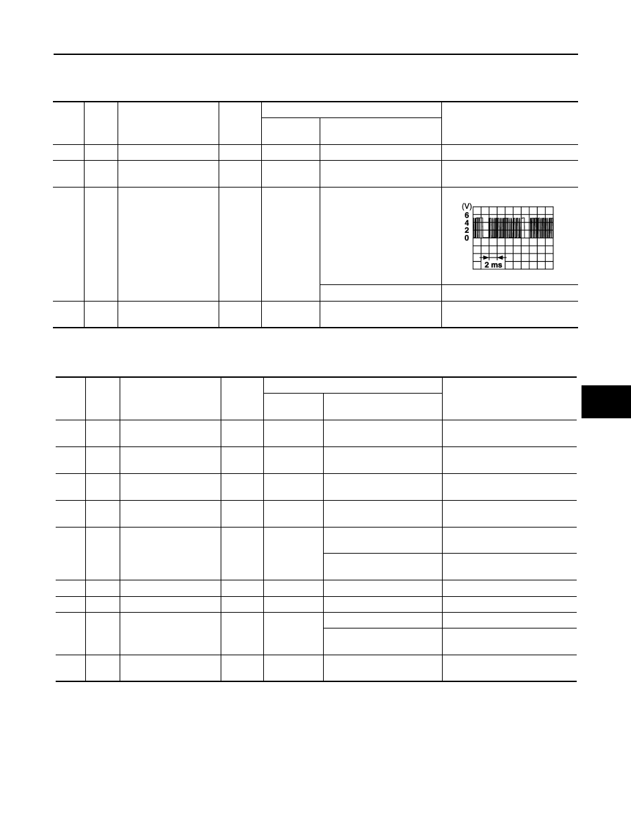
3
R/B
Steering lock unit com-
munication signal
Input
LOCK
Press ignition knob with Intel-
ligent Key inside vehicle.
Other than the above
5
4
Y/B
Steering lock unit
ground
—
—
—
0
SIIA1911J
Ter-
minal
Wire
color
Signal designation
Signal
Input/
output
Measuring condition
Voltage (V)
(Approx.)
Ignition knob
position
Operation or conditions
1
R/W
Steering lock unit power
supply
Output
LOCK
—
5
2
L
CAN-H
Input/
Output
—
—
—
3
P
CAN-L
Input/
Output
—
—
—
6
W
Ignition power supply
(ON)
Input
ON
Ignition knob ON or START
position
Battery voltage
7
B/W
Key switch
Input
LOCK
Insert mechanical key into
ignition key cylinder.
Battery voltage
Remove mechanical key
from ignition key cylinder.
0
11
L/R
Power source (Fuse)
Input
—
—
Battery voltage
12
B
Ground
—
—
—
0
27
L/W
Ignition knob switch
Input
—
Press ignition knob.
Battery voltage
Return ignition knob to
LOCK position.
0
31
Y/B
Steering lock unit
ground
—
—
—
0

BL-192
< SERVICE INFORMATION >
IVIS (INFINITI VEHICLE IMMOBILIZER SYSTEM-NATS)
Terminal and Reference Value for BCM
INFOID:0000000001327929
*: With Intelligent Key system
CONSULT-III Function
INFOID:0000000001327930
CONSULT-III DIAGNOSTIC TEST MODE FUNCTION
NATS SELF-DIAGNOSTIC RESULT ITEM CHART
32
R/B
Steering lock unit com-
munication signal
Output
LOCK
Press ignition knob with In-
telligent Key inside vehicle.
Other than the above
5
Ter-
minal
Wire
color
Signal designation
Signal
Input/
output
Measuring condition
Voltage (V)
(Approx.)
Ignition knob
position
Operation or conditions
SIIA1911J
Ter-
minal
Wire
color
Signal designation
Signal
Input/
output
Measuring condition
Voltage (V)
(Approx.)
Ignition knob
position
Operation or conditions
21
G/B
NATS antenna amp.
Input/
Output
—
Ignition knob OFF
→
ON po-
sition
Tester pointer should move just
after turning ignition knob “ON”
23
G/OR
Security indicator lamp
Output
LOCK
Goes OFF
→
illuminates (Ev-
ery 2.4 seconds)
Battery voltage
→
0
25
BR
NATS antenna amp.
Input/
Output
—
Ignition knob or switch OFF
→
ON position
Tester pointer should move just
after turning ignition knob “ON”
37*
B/W
Key switch
Input
—
Insert mechanical key into ig-
nition key cylinder
Battery voltage
Remove mechanical key
from ignition key cylinder
0
38
W/L
Ignition power supply
(ON)
Input
ON
Ignition knob ON or START
position
Battery voltage
39
L
CAN-H
Input/
Output
—
—
—
40
P
CAN-L
Input/
Output
—
—
—
42
L/R
Power source (Fuse)
Input
—
—
Battery voltage
49
B
Ground
—
—
—
0
52
B
Ground
—
—
—
0
55
G
Power source (Fuse)
Input
—
—
Battery voltage
CONSULT-III DIAGNOSTIC TEST MODE
Description
C/U INITIALIZATION
When replacing any of the following three components, C/U initialization is necessary.
[IVIS (NATS) ignition key/ BCM/ ECM]
SELF- DIAGNOSTIC RESULTS
Detected items (screen terms) are as shown in the chart.
PIN READ
Individual control unit number can be read.
For future information, refer to operation manual NATS-IVIS/NVIS

IVIS (INFINITI VEHICLE IMMOBILIZER SYSTEM-NATS)
BL-193
< SERVICE INFORMATION >
C
D
E
F
G
H
J
K
L
M
A
B
BL
N
O
P
Detected items (Screen terms)
P No.Code
(Self-diagnostic re-
sult of “ENGINE”)
Description
Diagnostic procedure
CHAIN OF ECM-IMMU
P1612
Communication impossible between
ECM and BCM.
Refer to
DIFFERENCE OF KEY
P1615
BCM can receive the key ID signal but the
result of ID verification between key ID
and BCM is NG.
Refer to
CHAIN OF IMMU-KEY
P1614
BCM cannot receive the key ID signal.
Refer to
ID DISCORD, IMM-ECM
P1611
The result of ID verification between BCM
and ECM is NG. System initialization is
required.
Refer to
LOCK MODE
P1610
When the starting operation is carried out
5 or more times consecutively under the
following conditions, IVIS(NATS) will shift
the mode to prevent the engine start.
• unregistered ignition key is used (with-
out intelligent key system)
• BCM or ECM malfunctioning
Refer to
DON'T ERASE BEFORE CHECK-
ING ENG DIAG
—
Engine trouble data and IVIS (NATS)
trouble data have been detected in ECM.
Refer to
.
BL-194
< SERVICE INFORMATION >
IVIS (INFINITI VEHICLE IMMOBILIZER SYSTEM-NATS)
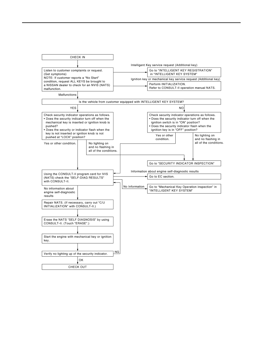
Diagnosis Procedure
INFOID:0000000001327931
WORK FLOW
MIIB0391E
Нет комментариевНе стесняйтесь поделиться с нами вашим ценным мнением.
Текст