Infiniti FX35 / FX45. Manual — part 739
GW-40
< SERVICE INFORMATION >
POWER WINDOW SYSTEM
5.
CHECK ENCODER SIGNAL
1.
Connect front power window motor (driver side) connector.
2.
Turn ignition switch ON.
3.
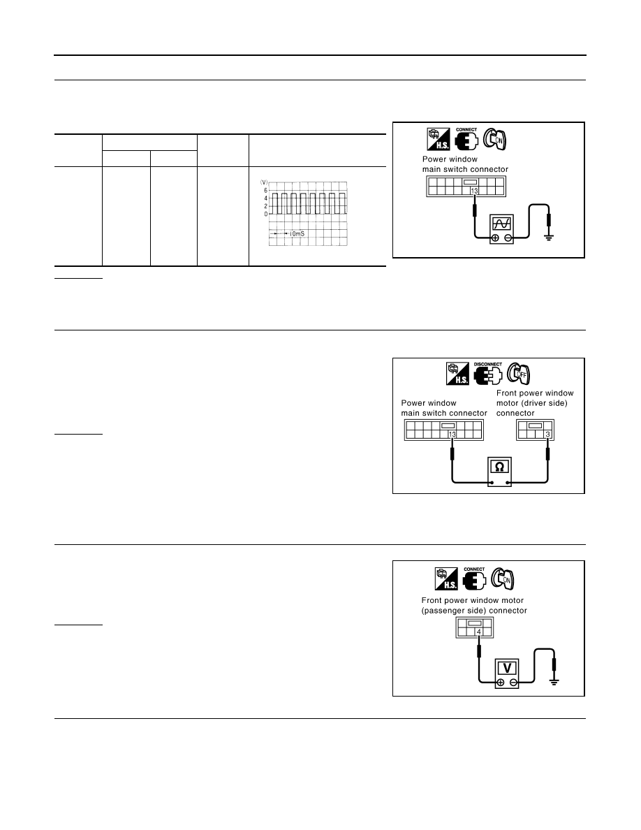
Check signal between power window main switch connector and ground with oscilloscope.
OK or NG
OK
>> Replace power window main switch.
NG
>> GO TO 6.
6.
CHECK HARNESS CONTINUITY 3
1.
Turn ignition switch OFF.
2.
Disconnect power window main switch and front power window motor (driver side) connector.
3.
Check continuity between power window main switch connector
D6 terminal 13 and front power window motor (driver side) con-
nector D8 terminal 3.
OK or NG
OK
>> Replace front power window motor (driver side).
NG
>> Repair or replace harness.
Check Encoder Circuit (Passenger Side)
INFOID:0000000001327984
1.
CHECK FRONT POWER WINDOW MOTOR (PASSENGER SIDE) POWER SUPPLY
1.
Turn ignition switch ON.
2.
Check voltage between front power window motor (passenger
side) connector D38 terminal 4 and ground.
OK or NG
OK
>> GO TO 3.
NG
>> GO TO 2.
2.
CHECK HARNESS CONTINUITY 1
1.
Turn ignition switch OFF.
2.
Disconnect front power window switch (passenger side) and front power window motor (passenger side)
connector.
Connec-
tor
Terminals (Wire color)
Condition
Signal
(Reference value)
(+)
(-)
D6
13 (PU)
Ground
Window
DOWN
PIIA4205E
OCC3383D
13 (PU) – 3 (PU)
: Continuity should exist.
PIIA9975E
4 (R) – Ground
: Approx.10V
PIIA9976E
POWER WINDOW SYSTEM
GW-41
< SERVICE INFORMATION >
C
D
E
F
G
H
J
K
L
M
A
B
GW
N
O
P
3.
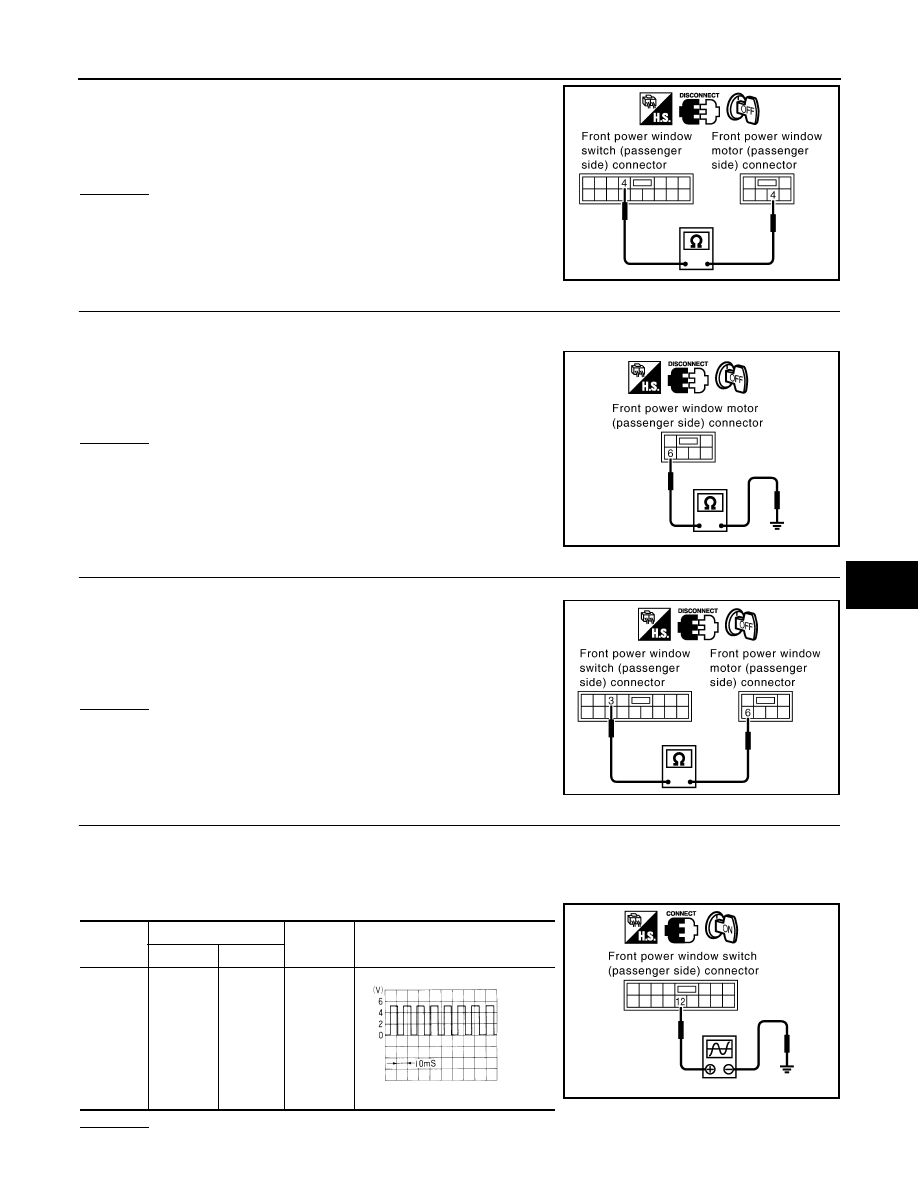
Check continuity between front power window switch (passen-
ger side) connector D36 terminal 4 and front power window
motor (passenger side) connector D38 terminal 4.
OK or NG
OK
>> Replace front power window switch (passenger side).
NG
>> Repair or replace harness.
3.
CHECK GROUND CIRCUIT
1.
Turn ignition switch OFF.
2.
Disconnect front power window motor (passenger side) connector.
3.
Check continuity between front power window motor (passenger
side) connector D38 terminal 6 and ground.
OK or NG
OK
>> GO TO 5.
NG
>> GO TO 4.
4.
CHECK HARNESS CONTINUITY 2
1.
Disconnect front power window switch (passenger side) connector.
2.
Check continuity between front power window switch (passen-
ger side) connector D36 terminal 3 and front power window
motor (passenger side) connector D38 terminal 6.
OK or NG
OK
>> Replace front power window switch (passenger side).
NG
>> Repair or replace harness.
5.
CHECK ENCODER SIGNAL
1.
Connect front power window motor (passenger side) connector.
2.
Turn ignition switch ON.
3.
Check signal between front power window switch (passenger side) connector and ground with oscillo-
scope.
OK or NG
4 (R) – 4 (R)
: Continuity should exist.
PIIA9977E
6 (SB) – Ground
: Continuity should exist.
PIIA9966E
3 (SB) – 6 (SB)
: Continuity should exist.
PIIA9967E
Connec-
tor
Terminals (Wire color)
Condition
Signal
(Reference value)
(+)
(-)
D36
12 (PU)
Ground
Window
DOWN
PIIA4209E
OCC3383D
GW-42
< SERVICE INFORMATION >
POWER WINDOW SYSTEM
OK
>> Replace front power window switch (passenger side).
NG
>> GO TO 6.
6.
CHECK HARNESS CONTINUITY 3
1.
Turn ignition switch OFF.
2.
Disconnect front power window switch (passenger side) and front power window motor (passenger side)
connector.
3.
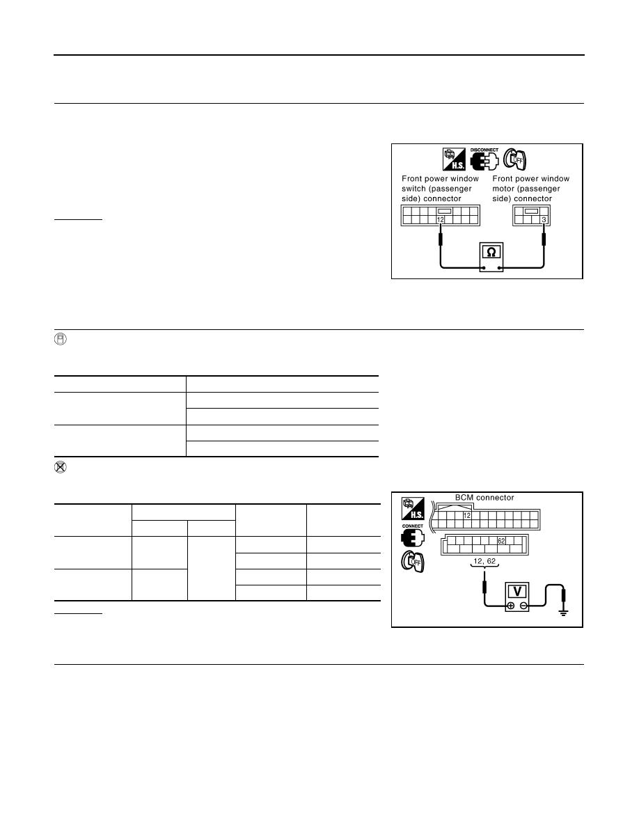
Check continuity between front power window switch (passen-
ger side) connector D36 terminal 12 and front power window
motor (passenger side) connector D38 terminal 3.
OK or NG
OK
>> Replace front power window motor (passenger side).
NG
>> Repair or replace harness.
Check Door Switch
INFOID:0000000001327985
1.
CHECK DOOR SWITCH INPUT SIGNAL
With CONSULT-III
Check (“DOOR SW-DR” and “DOOR SW-AS”) in “DATA MONITOR” mode with CONSULT-III.
Without CONSULT-III
Check voltage between BCM connector M3, B14 terminals 12, 62 and ground.
OK or NG
OK
>> Door switch is OK.
NG
>> GO TO 2.
2.
CHECK HARNESS CONTINUITY
1.
Turn ignition switch OFF.
2.
Disconnect door switch and BCM connector.
12 (PU) – 3 (PU)
: Continuity should exist.
PIIA9978E
Monitor item
Condition
DOOR SW-DR
OPEN
: ON
CLOSE
: OFF
DOOR SW-AS
OPEN
: ON
CLOSE
: OFF
Item
Terminals (Wire color)
Door condition
Voltage [V]
(Approx.)
(+)
(–)
Passenger side
door switch
12 (P/B)
Ground
OPEN
0
CLOSE
Battery voltage
Driver side door
switch
62 (W)
OPEN
0
CLOSE
Battery voltage
PIIA6158E
POWER WINDOW SYSTEM
GW-43
< SERVICE INFORMATION >
C
D
E
F
G
H
J
K
L
M
A
B
GW
N
O
P
3.
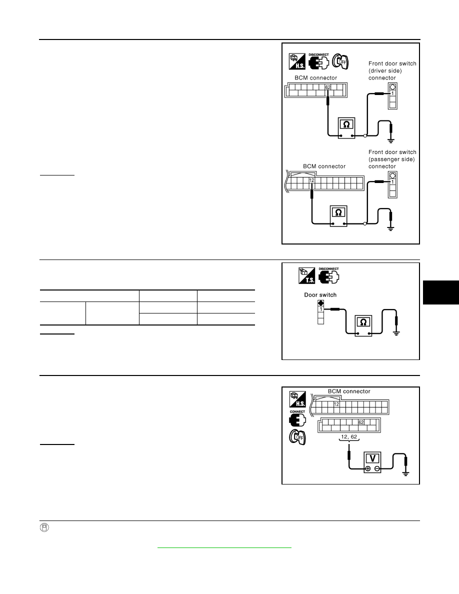
Check continuity between BCM connector M3, B14 terminals
12, 62 and door switch connector B26, B36 terminal 1.
4.
Check continuity between BCM connector M3, B14 terminals
12, 62 and ground.
OK or NG
OK
>> GO TO 3.
NG
>> Repair or replace harness.
3.
CHECK DOOR SWITCH
Check continuity between door switches terminal 1 and ground part
of door switch.
OK or NG
OK
>> GO TO 4.
NG
>> Replace malfunction door switch.
4.
CHECK BCM OUTPUT SIGNAL
1.
Connect BCM connector.
2.
Check voltage between BCM connector M3, B14 terminals 12,
62 and ground.
OK or NG
OK
>> Further inspection is necessary, Refer to symptom
chart.
NG
>> Replace BCM.
Check Front Door Key Cylinder Switch
INFOID:0000000001327986
1.
CHECK DOOR KEY CYLINDER SWITCH INPUT SIGNAL
With CONSULT-III
Check (“KEY CYL LK-SW”, “KEY CYL UN-SW”) in “DATA MONITOR” mode for “POWER DOOR ROCK SYS-
TEM” with CONSULT-III. Refer to
BL-36, "CONSULT-III Function (BCM)"
Driver side door
62 (W) – 1 (W)
: Continuity should exist.
Passenger side door
12 (P/B) – 1 (SB)
: Continuity should exist.
12 (P/B) – Ground
: Continuity should not exist.
62 (W) – Ground
: Continuity should not exist.
PIIA6159E
Terminal
Door switch
Continuity
1
Ground part of
door switch
Pushed
No
Released
Yes
PIIA3351E
12 (P/B) – Ground
: Battery voltage
62 (W) – Ground
: Battery voltage
PIIA6158E
Нет комментариевНе стесняйтесь поделиться с нами вашим ценным мнением.
Текст