Infiniti FX35 / FX45. Manual — part 16

ACS-58
< SERVICE INFORMATION >
[ICC]
TROUBLE DIAGNOSIS FOR SYMPTOMS
• Chime does not sound when the system does not detect any vehicle ahead. (Diagnose the conditions under
which the system is detecting the vehicle ahead and when the system is malfunctioning. If there is any mal-
function in detecting the vehicle ahead, check the system following the
Frequently Cannot Detect the Vehicle Ahead/ Detection Zone Is Short"
.
1.
CHECK ICC WARNING CHIME
With “Active Test” of “ICC”, check that ICC warning chime operates normally.
OK or NG
OK
>> Determine preceding vehicle detection status when malfunction occurred. If chime should have
sounded: after replacing ICC unit. Perform ICC system running test, and then perform self-diag-
nosis of ICC system again.
NG
>> GO TO 2.
2.
PERFORM SELF-DIAGNOSIS OF ICC SYSTEM
1.
Perform self-diagnosis of ICC system.
2.
Check if “DTC 20 CAN COMM CIRCUIT” is indicated.
Is it indicated?
YES
>> Refer to
ACS-36, "DTC 20 CAN COMM CIRCUIT"
.
NO
>> GO TO 3.
3.
PERFORM SELF-DIAGNOSIS OF UNIFIED METER AND A/C AMP.
Perform self-diagnosis of unified meter and A/C amp. Refer to
DI-27, "CONSULT-III Function (METER/M&A)"
.
OK or NG
OK
>> 1.
Replace combination meter.
2.
Erase DTC and perform ICC system running test. Then perform self-diagnosis of ICC system
again.
NG
>> 1.
Repair or replace applicable item.
2.
Erase DTC and perform ICC system running test. Then perform self-diagnosis of ICC system
again.
Symptom 6 Driving Force Is Hunting
INFOID:0000000001328854
1.
CHECK SELF-DIAGNOSIS OF ECM
Perform self-diagnosis of ECM.
OK or NG
OK
>> Refer to
ACS-58, "Symptom 7 ICC System Frequently Cannot Detect the Vehicle Ahead/ Detec-
NG
>> 1.
Repair or replace applicable parts.
2.
Erase DTC and perform ICC system running test. Then perform self-diagnosis of ICC system
again.
Symptom 7 ICC System Frequently Cannot Detect the Vehicle Ahead/ Detection Zone
Is Short
INFOID:0000000001328855
The detection function may become unstable in the following cases.
• When the reflector of the vehicle ahead is deficient/ not clean enough to reflect the radar.
• When driving a road with extremely sharp corners.
• When the radar cannot detect the reflector of the vehicle ahead as the vehicle ahead is passing a hill or
passing the peak.
1.
VISUAL CHECK
Check ICC sensor body window for contamination and foreign materials.
OK or NG
OK
>> If any contamination or foreign materials are found, remove them. Then perform ICC system run-
ning test.
NG
>> GO TO 2.
2.
CHECK FUNCTION

TROUBLE DIAGNOSIS FOR SYMPTOMS
ACS-59
< SERVICE INFORMATION >
[ICC]
C
D
E
F
G
H
I
J
L
M
A
B
ACS
N
O
P
After adjusting ICC sensor beam aiming, perform ICC system running test. Check that preceding vehicle
detection performance has been improved.
OK or NG
OK
>> INSPECTION END
NG
>> 1.
Replace ICC sensor, and perform laser beam aiming adjustment.
2.
Erase DTC and perform ICC system running test. Then perform self-diagnosis of ICC system
again.
Symptom 8 the System Does Not Detect the Vehicle Ahead at All
INFOID:0000000001328856
1.
VISUAL CHECK 1
With ignition switch turned ON (engine not started), check that all indicator lamps in ICC system display are
continuously lit. (Check for a missing segment in preceding vehicle detection display.)
OK or NG
OK
>> GO TO 2.
NG
>> Check for combination meter. Refer to
.
2.
VISUAL CHECK 2
Check ICC sensor body window for contamination and foreign materials.
OK or NG
OK
>> If any contamination or foreign materials are found, remove them. Perform ICC system running
test.
NG
>> GO TO 3.
3.
VISUAL CHECK 3
Check ICC sensor body window for cracks and scratches.
OK or NG
OK
>> GO TO 4.
NG
>> 1.
Replace ICC sensor, and perform laser beam aiming adjustment.
2.
Erase DTC and perform ICC system running test. Then perform self-diagnosis of ICC system
again.
4.
ADJUST ICC SENSOR
After adjusting ICC sensor beam aiming, perform ICC system running test. Check that preceding vehicle
detection performance has been improved.
OK or NG
OK
>> INSPECTION END
NG
>> 1.
Replace ICC sensor, and perform laser beam aiming adjustment.
2.
Erase DTC and perform ICC system running test. Then perform self-diagnosis of ICC system
again.
SELF-DIAGNOSIS BY ICC SYSTEM DISPLAY WILL NOT RUN
INFOID:0000000001544638
PKIB4144E
ACS-60
< SERVICE INFORMATION >
[ICC]
TROUBLE DIAGNOSIS FOR SYMPTOMS
Possible Irregular Condition
1.
CHECK FUSES
Check that any of the fuses is blown.
OK or NG
OK
>> GO TO 2.
NG
>> If fuse is blown, be sure to eliminate cause of malfunction before installing new fuse.
2.
CHECK ICC SYSTEM DISPLAY
1.
Turn ignition switch ON.
2.
Check if all displays illuminate.
Do all displays illuminate?
YES
>> GO TO 3.
NO
>> GO TO 6.
3.
CHECK HARNESS BETWEEN ECM AND ICC STEERING SWITCH
1.
Turn ignition switch OFF.
2.
Disconnect ECM connector, and check terminals for bend and
looseness.
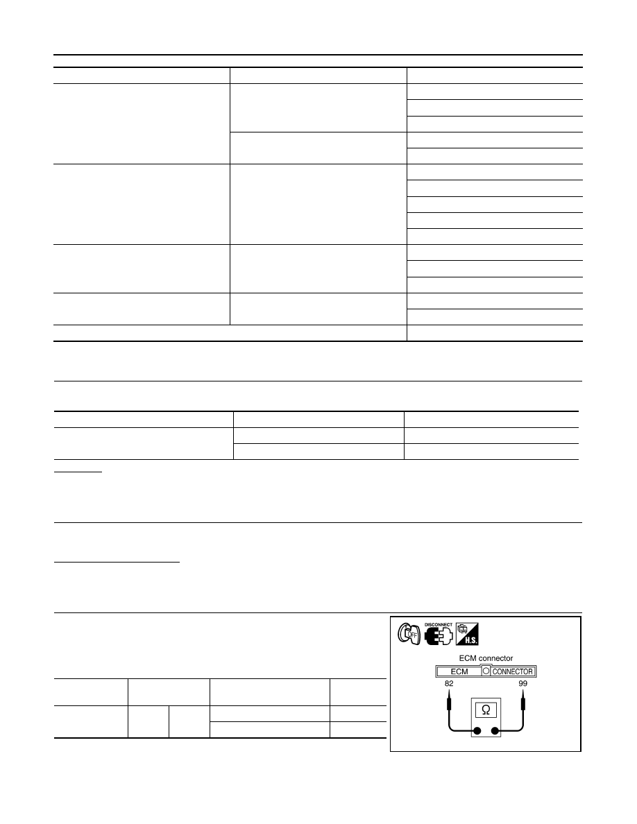
3.
Check continuity between ECM harness connector terminals.
Open or short lines
Symptoms
Malfunction causes
ICC unit power supply malfunction
No voltage supply from ignition switch
Fuse blown
Harness open
Harness shorted
Ground cable not connected
Harness open
Harness shorted
ICC steering switch malfunction
No signal transmitted
Harness open
Harness shorted
Spiral cable open
Spiral cable shorted
Switch or ECM malfunction
CAN communication system malfunction
Signal not transmitted
Harness open
Harness shorted
CAN communication outside the standard.
Combination meter system malfunction
Indication not possible
Indicator display malfunction
ICC system display segments disappear.
ICC unit malfunction
ICC unit internal malfunction.
Unit
Power source
Fuse No.
ICC unit
Ignition switch (ON)
12
Battery
35
ECM connector
Terminal
Condition
Resistance
(Approx.)
M90
82
99
When MAIN switch pressed
0
Ω
When MAIN switch released
5.5 k
Ω
PKIB4145E
TROUBLE DIAGNOSIS FOR SYMPTOMS
ACS-61
< SERVICE INFORMATION >
[ICC]
C
D
E
F
G
H
I
J
L
M
A
B
ACS
N
O
P
4.
Check continuity between ECM harness connector and ground.
OK or NG
OK
>> GO TO 5.
NG
>> GO TO 4.
4.
CHECK ICC STEERING SWITCH
Check ICC steering switch. Refer to
OK or NG
OK
>> 1.
Repair or replace harness between ECM and ICC steering switch.
2.
Perform self-diagnosis mode for ICC system.
NG
>> 1.
Replace ICC steering switch.
2.
Perform self-diagnosis mode for ICC system.
5.
CHECK SELF-DIAGNOSIS
1.
Connect ECM connector.
2.
Turn ignition switch ON.
3.
Perform self-diagnosis mode for ICC system.
OK or NG
OK
>> INSPECTION END
NG
>> GO TO 6.
6.
CHECK CONNECTOR FOR ICC UNIT
1.
Turn ignition switch OFF.
2.
Disconnect ICC unit connector, and check terminals for bend and looseness.
3.
Connect ICC unit connector.
4.
Turn ignition switch ON.
5.
Check if all displays illuminate.
Do all displays illuminate?
YES
>> Perform self-diagnosis again.
NO
>> GO TO 7.
7.
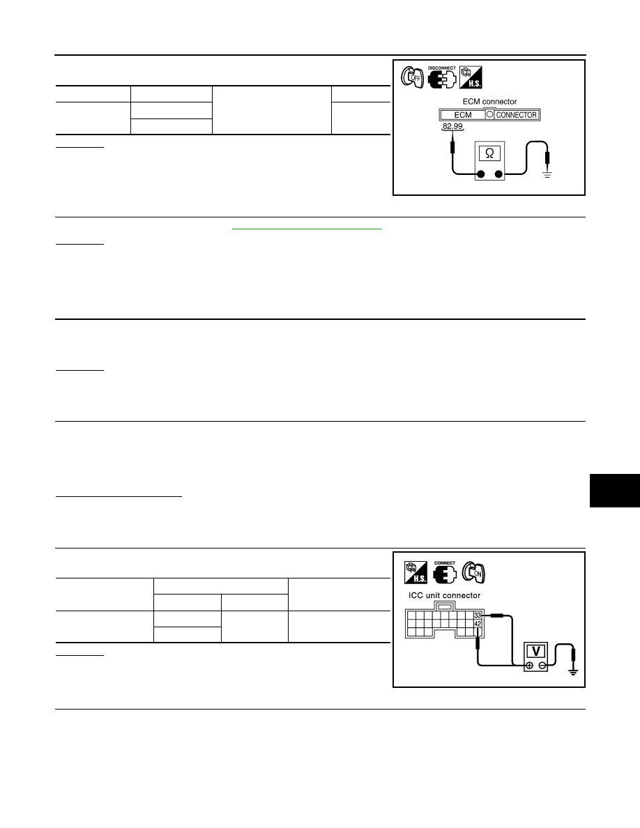
CHECK POWER SUPPLY CIRCUIT FOR ICC UNIT
Check voltage between ICC unit harness connector terminals.
OK or NG
OK
>> GO TO 8.
NG
>> Repair ICC unit power supply harness.
8.
CHECK GROUND CIRCUIT FOR ICC UNIT
ECM connector
Terminal
Ground
Continuity
M90
82
No
99
PKIB4146E
ICC unit connector
Terminal
Voltage (Approx.)
(+)
(
−
)
M89
33
Ground
Battery voltage
42
SKIA1173E
Нет комментариевНе стесняйтесь поделиться с нами вашим ценным мнением.
Текст