Infiniti FX35 / FX45. Manual — part 372
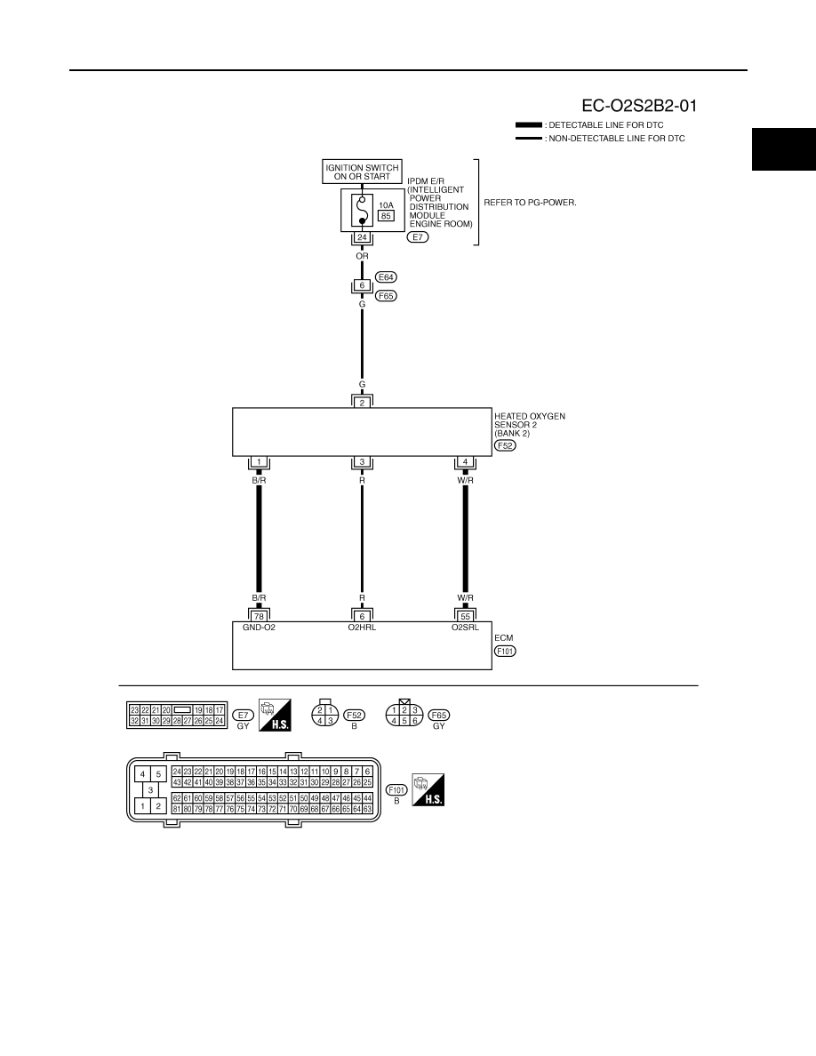
DTC P0137, P0157 HO2S2
EC-249
< SERVICE INFORMATION >
[VQ35DE]
C
D
E
F
G
H
I
J
K
L
M
A
EC
N
P
O
BANK 2
Specification data are reference values and are measured between each terminal and ground.
CAUTION:
Do not use ECM ground terminals when measuring input/output voltage. Doing so may result in dam-
age to the ECM's transistor. Use a ground other than ECM terminals, such as the ground.
TBWM1593E
EC-250
< SERVICE INFORMATION >
[VQ35DE]
DTC P0137, P0157 HO2S2
Diagnosis Procedure
INFOID:0000000001326080
1.
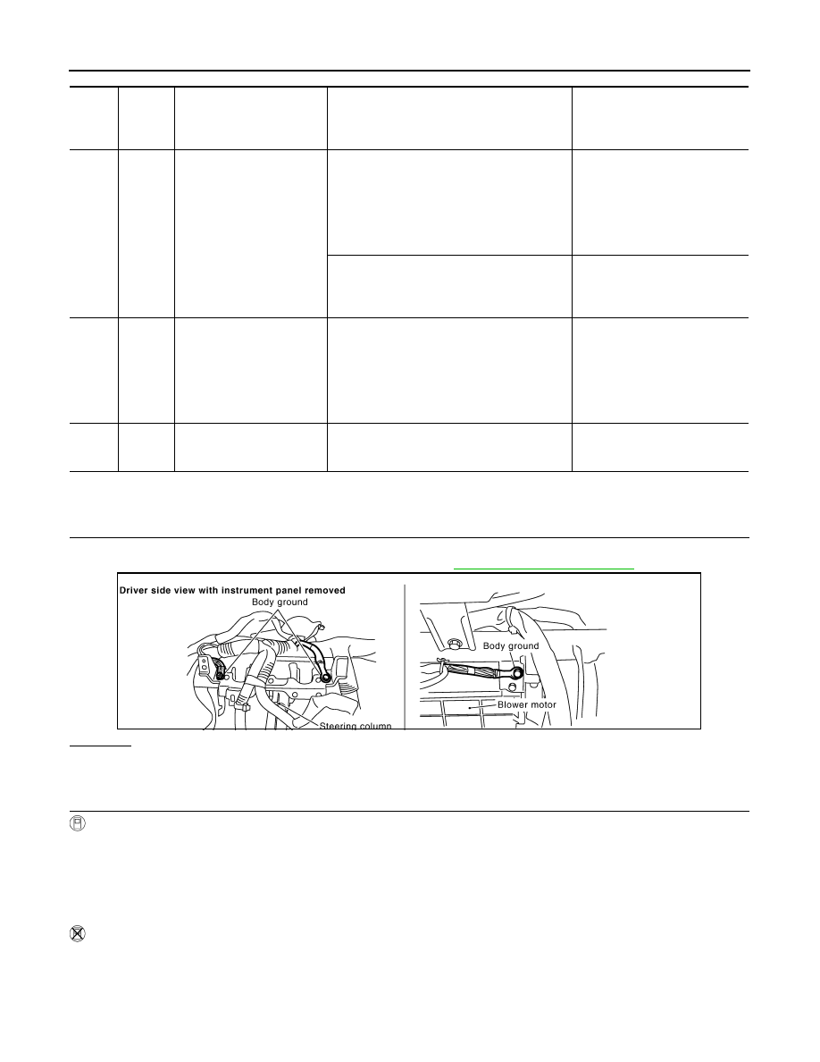
CHECK GROUND CONNECTIONS
1.
Turn ignition switch OFF.
2.
Loosen and retighten ground screw on the body. Refer to
OK or NG
OK
>> GO TO 2.
NG
>> Repair or replace ground connections.
2.
CLEAR THE SELF-LEARNING DATA
With CONSULT-III
1.
Start engine and warm it up to normal operating temperature.
2.
Select “SELF-LEARNING CONT” in “WORK SUPPORT” mode with CONSULT-III.
3.
Clear the self-learning control coefficient by touching “CLEAR”.
4.
Run engine for at least 10 minutes at idle speed.
Is the 1st trip DTC P0171 or P0174 detected?
Is it difficult to start engine?
Without CONSULT-III
1.
Start engine and warm it up to normal operating temperature.
2.
Turn ignition switch OFF.
TER-
MI-
NAL
NO.
WIRE
COLOR
ITEM
CONDITION
DATA (DC Voltage)
6
R
Heated oxygen sensor 2
heater (bank 2)
[Engine is running]
• Engine speed: Below 3,600 rpm after the fol-
lowing conditions are met
- Engine: After warming up
- Keeping the engine speed between 3,500
and 4,000 rpm for 1 minute and at idle for 1
minute under no load
0 - 1.0V
[Ignition switch: ON]
• Engine stopped
[Engine is running]
• Engine speed: Above 3,600 rpm
BATTERY VOLTAGE
(11 - 14V)
55
W/R
Heated oxygen sensor 2
(bank 2)
[Engine is running]
• Revving engine from idle to 3,000 rpm quick-
ly after the following conditions are met
- Engine: After warming up
- Keeping the engine speed between 3,500
and 4,000 rpm for 1 minute and at idle for 1
minute under no load
0 - Approximately 1.0V
78
B/R
Sensor ground
(Heated oxygen sensor)
[Engine is running]
• Warm-up condition
• Idle speed
Approximately 0V
PBIB2625E
DTC P0137, P0157 HO2S2
EC-251
< SERVICE INFORMATION >
[VQ35DE]
C
D
E
F
G
H
I
J
K
L
M
A
EC
N
P
O
3.
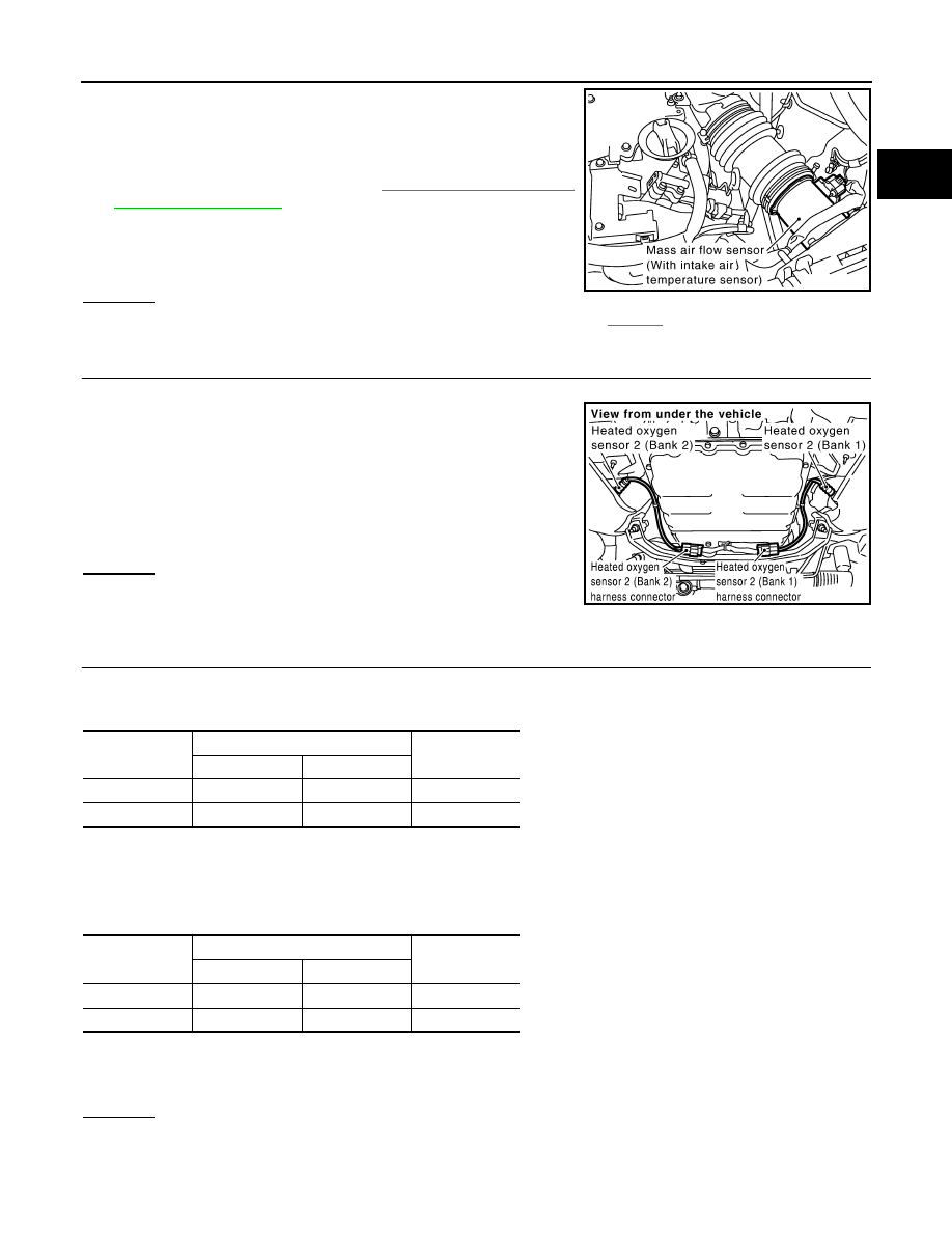
Disconnect mass air flow sensor harness connector, and restart
and run engine for at least 5 seconds at idle speed.
4.
Stop engine and reconnect mass air flow sensor harness con-
nector.
5.
Make sure DTC P0102 is displayed.
6.
Erase the DTC memory. Refer to
7.
Make sure DTC P0000 is displayed.
8.
Run engine for at least 10 minutes at idle speed.
Is the 1st trip DTC P0171 or P0174 detected?
Is it difficult to start engine?
Yes or No
Yes
>> Perform trouble diagnosis for DTC P0171or P0174. Refer to
.
No
>> GO TO 3.
3.
CHECK HEATED OXYGEN SENSOR 2 GROUND CIRCUIT FOR OPEN AND SHORT
1.
Turn ignition switch OFF.
2.
Disconnect heated oxygen sensor 2 harness connector.
3.
Disconnect ECM harness connector.
4.
Check harness continuity between HO2S2 terminal 1 and ECM
terminal 78.
Refer to Wiring Diagram.
5.
Also check harness for short to ground and short to power.
OK or NG
OK
>> GO TO 4.
NG
>> Repair open circuit or short to ground or short to power
in harness or connectors.
4.
CHECK HEATED OXYGEN SENSOR 2 INPUT SIGNAL CIRCUIT FOR OPEN AND SHORT
1.
Check harness continuity between ECM terminal and HO2S2 terminal as follows.
Refer to Wiring Diagram.
2.
Check harness continuity between the following terminals and ground.
Refer to Wiring Diagram.
3.
Also check harness for short to ground and short to power.
OK or NG
OK
>> GO TO 5.
NG
>> Repair open circuit or short to ground or short to power in harness or connectors.
PBIB1565E
Continuity should exist.
PBIB1576E
DTC
Terminals
Bank
ECM
Sensor
P0137
74
4
1
P0157
55
4
2
Continuity should exist.
DTC
Terminals
Bank
ECM
Sensor
P0137
74
4
1
P0157
55
4
2
Continuity should not exist.
EC-252
< SERVICE INFORMATION >
[VQ35DE]
DTC P0137, P0157 HO2S2
5.
CHECK HEATED OXYGEN SENSOR 2
EC-252, "Component Inspection"
OK or NG
OK
>> GO TO 6.
NG
>> Replace malfunctioning heated oxygen sensor 2.
6.
CHECK INTERMITTENT INCIDENT
>> INSPECTION END
Component Inspection
INFOID:0000000001326081
HEATED OXYGEN SENSOR 2
With CONSULT-III
1.
Turn ignition switch ON and select “DATA MONITOR” mode with CONSULT-III.
2.
Start engine and warm it up to the normal operating temperature.
3.
Turn ignition switch OFF and wait at least 10 seconds.
4.
Start engine and keep the engine speed between 3,500 and 4,000 rpm for at least 1 minute under no load.
5.
Let engine idle for 1 minute.
6.
Select “FUEL INJECTION” in “ACTIVE TEST” mode, and select “HO2S2 (B1)/(B2)” as the monitor item
with CONSULT-III.
7.
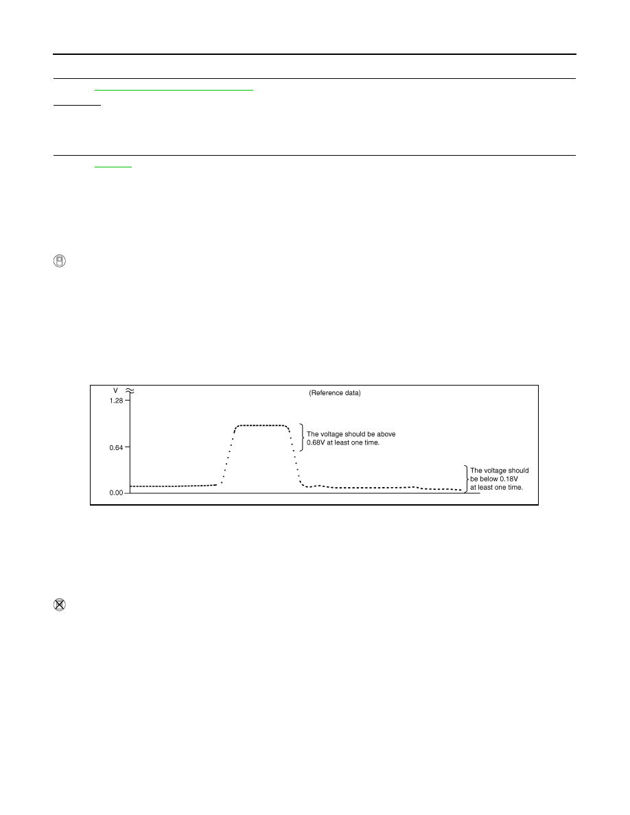
Check “HO2S2 (B1)/(B2)” at idle speed when adjusting “FUEL INJECTION” to
±
25%.
“HO2S2 (B1)/(B2)” should be above 0.68V at least once when the “FUEL INJECTION” is +25%.
“HO2S2 (B1)/(B2)” should be below 0.18V at least once when the “FUEL INJECTION” is
−
25%.
CAUTION:
• Discard any heated oxygen sensor which has been dropped from a height of more than 0.5 m (19.7
in) onto a hard surface such as a concrete floor; use a new one.
• Before installing new oxygen sensor, clean exhaust system threads using Oxygen Sensor Thread
Cleaner tool J-43897-18 or J-43897-12 and approved anti-seize lubricant.
Without CONSULT-III
1.
Start engine and warm it up to the normal operating temperature.
2.
Turn ignition switch OFF and wait at least 10 seconds.
3.
Start engine and keep the engine speed between 3,500 and 4,000 rpm for at least 1 minute under no load.
4.
Let engine idle for 1 minute.
5.
Set voltmeter probes between ECM terminal 74 [HO2S2 (B1) signal] or 55 [HO2S2 (B2) signal] and
ground.
PBIB3458E
Нет комментариевНе стесняйтесь поделиться с нами вашим ценным мнением.
Текст