Infiniti FX35 / FX45. Manual — part 580
DTC P1800 VIAS CONTROL SOLENOID VALVE
EC-1081
< SERVICE INFORMATION >
[VK45DE]
C
D
E
F
G
H
I
J
K
L
M
A
EC
N
P
O
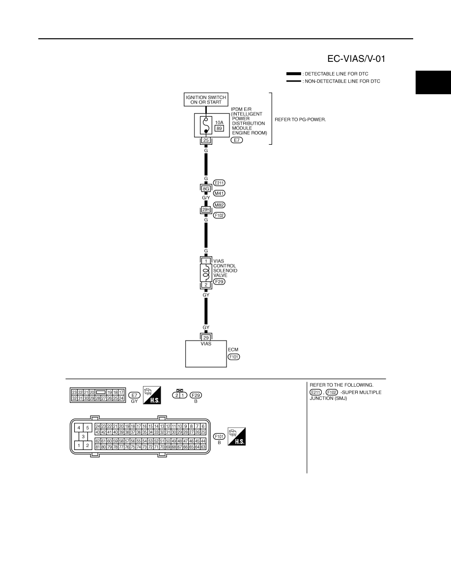
Wiring Diagram
INFOID:0000000001326965
Specification data are reference values and are measured between each terminal and ground.
CAUTION:
Do not use ECM ground terminals when measuring input/output voltage. Doing so may result in dam-
age to the ECM's transistor. Use a ground other than ECM terminals, such as the ground.
TBWM1358E
EC-1082
< SERVICE INFORMATION >
[VK45DE]
DTC P1800 VIAS CONTROL SOLENOID VALVE
Diagnosis Procedure
INFOID:0000000001326966
1.
CHECK VIAS CONTROL SOLENOID VALVE POWER SUPPLY CIRCUIT
1.
Turn ignition switch OFF.
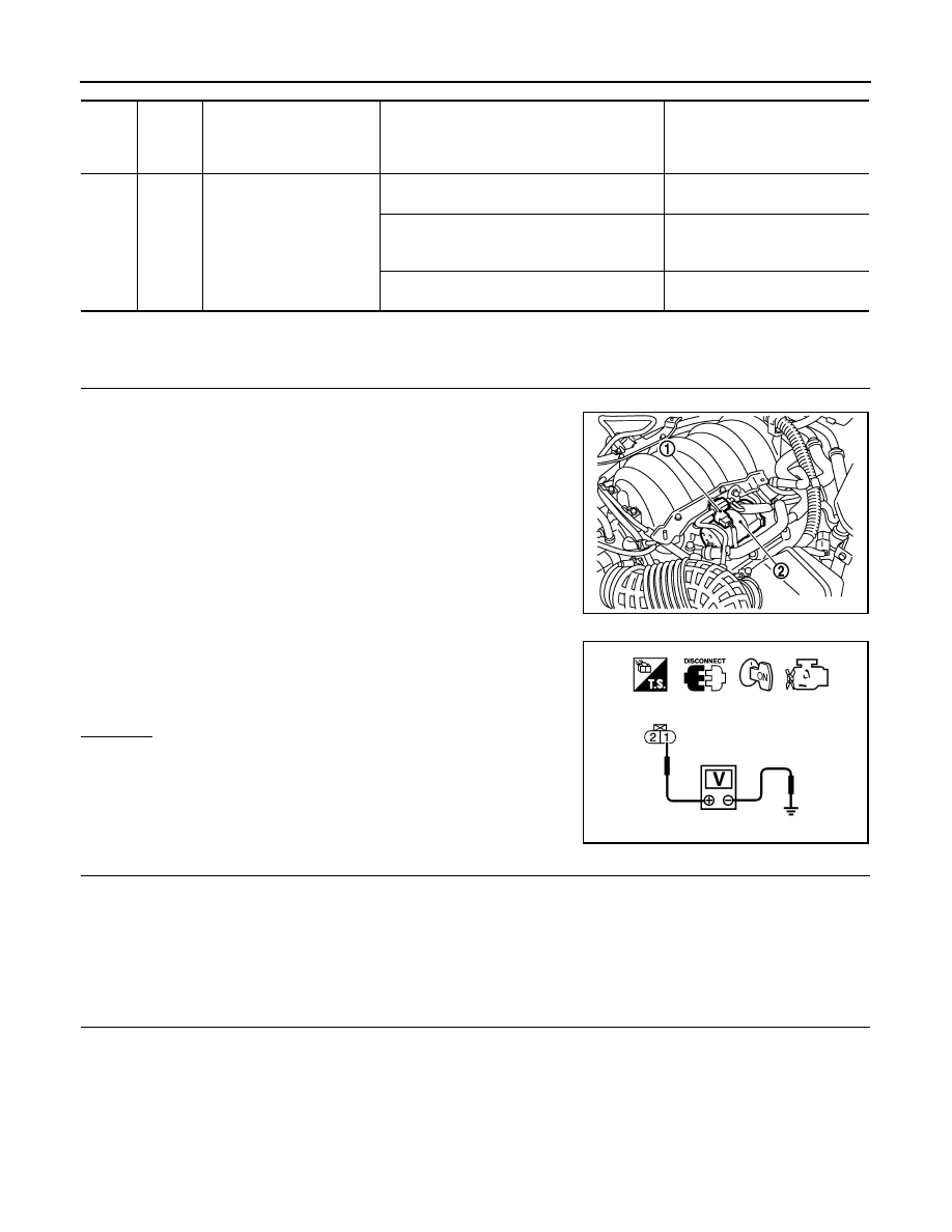
2.
Disconnect VIAS control solenoid valve (1) harness connector.
-
Vacuum tank (2)
3.
Turn ignition switch ON.
4.
Check voltage between VIAS control solenoid valve terminal 1
and ground with CONSULT-III or tester.
OK or NG
OK
>> GO TO 3.
NG
>> GO TO 2.
2.
DETECT MALFUNCTIONING PART
Check the following.
• Harness connectors E211, M41
• Harness connectors M82, F102
• Harness for open or short between VIAS control solenoid valve and IPDM E/R
>> Repair harness or connectors.
3.
CHECK VIAS CONTROL SOLENOID VALVE OUTPUT SIGNAL CIRCUIT FOR OPEN AND SHORT
1.
Turn ignition switch OFF.
2.
Disconnect ECM harness connector.
3.
Check harness continuity between ECM terminal 29 and VIAS control solenoid valve terminal 2.
Refer to Wiring Diagram.
4.
Also check harness for short to ground and short to power.
TER-
MI-
NAL
NO.
WIRE
COLOR
ITEM
CONDITION
DATA (DC Voltage)
29
GY
VIAS control solenoid valve
[Engine is running]
• Selector lever: P or N
0 - 1.0V
[Engine is running]
• Selector lever: D
• Engine speed: Below 5,000 rpm
BATTERY VOLTAGE
(11 - 14V)
[Engine is running]
• Engine speed: Above 5,000 rpm
0 - 1.0V
PBIB3236E
Voltage: Battery voltage
PBIB0173E
Continuity should exist.
DTC P1800 VIAS CONTROL SOLENOID VALVE
EC-1083
< SERVICE INFORMATION >
[VK45DE]
C
D
E
F
G
H
I
J
K
L
M
A
EC
N
P
O
OK or NG
OK
>> GO TO 4.
NG
>> Repair open circuit or short to ground or short to power in harness or connectors.
4.
CHECK VIAS CONTROL SOLENOID VALVE
EC-1083, "Component Inspection"
.
OK or NG
OK
>> GO TO 5.
NG
>> Replace VIAS control solenoid valve.
5.
CHECK INTERMITTENT INCIDENT
>> INSPECTION END
Component Inspection
INFOID:0000000001326967
VIAS CONTROL SOLENOID VALVE
With CONSULT-III
1.
Reconnect harness connectors disconnected.
2.
Turn ignition switch ON.
3.
Perform “VIAS SOL VALVE” in “ACTIVE TEST” mode.
4.
Check air passage continuity and operation delay time under the
following conditions.
Operation takes less than 1 second.
5.
If NG, replace VIAS control solenoid valve.
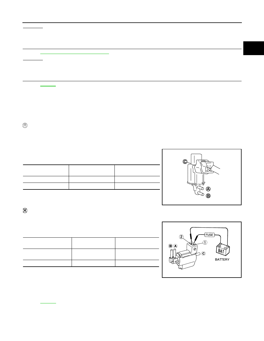
Without CONSULT-III
1.
Disconnect VIAS control solenoid valve.
2.
Check air passage continuity and operation delay time under the
following conditions.
Operation takes less than 1 second.
3.
If NG, replace VIAS control solenoid valve.
Removal and Installation
INFOID:0000000001326968
VIAS CONTROL SOLENOID VALVE
.
Condition
VIAS SOL VALVE
Air passage continuity
between A and B
Air passage continuity
between A and C
ON
Yes
No
OFF
No
Yes
JMBIA0180ZZ
Condition
Air passage continuity
between A and B
Air passage continuity
between A and C
12V direct current supply
between terminals 1 and 2
Yes
No
No supply
No
Yes
MEC488B

EC-1084
< SERVICE INFORMATION >
[VK45DE]
DTC P1805 BRAKE SWITCH
DTC P1805 BRAKE SWITCH
Description
INFOID:0000000001326969
Brake switch signal is applied to the ECM through the stop lamp switch when the brake pedal is depressed.
This signal is used mainly to decrease the engine speed when the vehicle is driving.
CONSULT-III Reference Value in Data Monitor Mode
INFOID:0000000001326970
Specification data are reference values.
On Board Diagnosis Logic
INFOID:0000000001326971
The MIL will not light up for this diagnosis.
FAIL-SAFE MODE
When the malfunction is detected, ECM enters fail-safe mode.
DTC Confirmation Procedure
INFOID:0000000001326972
1.
Turn ignition switch ON.
2.
Fully depress the brake pedal for at least 5 seconds.
3.
Erase the DTC with CONSULT-III.
4.
Check 1st trip DTC.
5.
If 1st trip DTC is detected, go to
EC-1086, "Diagnosis Procedure"
MONITOR ITEM
CONDITION
SPECIFICATION
BRAKE SW
• Ignition switch: ON
Brake pedal: Fully released
OFF
Brake pedal: Slightly depressed
ON
DTC No.
Trouble diagnosis name
DTC detecting condition
Possible cause
P1805
1805
Brake switch
A brake switch signal is not sent to ECM for ex-
tremely long time while the vehicle is driving.
• Harness or connectors
(Stop lamp switch circuit is open or short-
ed.)
• Stop lamp switch
Engine operating condition in fail-safe mode
ECM controls the electric throttle control actuator by regulating the throttle opening to a small range.
Therefore, acceleration will be poor.
Vehicle condition
Driving condition
When engine is idling
Normal
When accelerating
Poor acceleration
Нет комментариевНе стесняйтесь поделиться с нами вашим ценным мнением.
Текст