Infiniti FX35 / FX45. Manual — part 386
DTC P0222, P0223 TP SENSOR
EC-305
< SERVICE INFORMATION >
[VQ35DE]
C
D
E
F
G
H
I
J
K
L
M
A
EC
N
P
O
1.
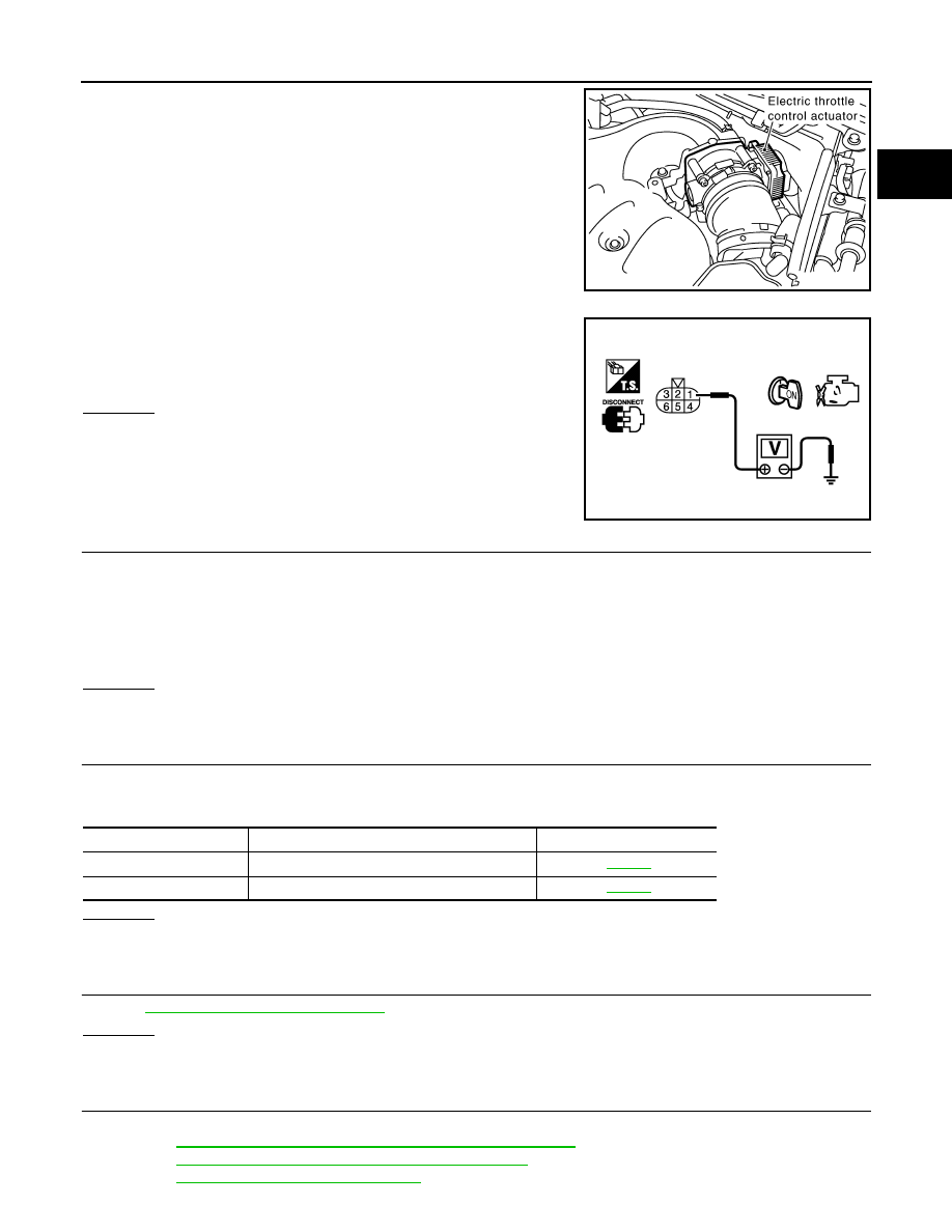
Disconnect electric throttle control actuator harness connector.
2.
Turn ignition switch ON.
3.
Check voltage between electric throttle control actuator terminal
1 and ground with CONSULT-III or tester.
OK or NG
OK
>> GO TO 7.
NG
>> GO TO 3.
3.
CHECK THROTTLE POSITION SENSOR 1 POWER SUPPLY CIRCUIT-II
1.
Turn ignition switch OFF.
2.
Disconnect ECM harness connector.
3.
Check harness continuity between electric throttle control actuator terminal 1 and ECM terminal 47.
Refer to Wiring Diagram.
OK or NG
OK
>> GO TO 4.
NG
>> Repair open circuit.
4.
CHECK THROTTLE POSITION SENSOR 1 POWER SUPPLY CIRCUIT-III
Check the following.
• Harness for short to power and short to ground, between the following terminals.
OK or NG
OK
>> GO TO 5.
NG
>> Repair short to ground or short to power in harness or connectors.
5.
CHECK APP SENSOR
EC-517, "Component Inspection"
OK or NG
OK
>> GO TO 11.
NG
>> GO TO 6.
6.
REPLACE ACCELERATOR PEDAL ASSEMBLY
1.
Replace accelerator pedal assembly.
2.
EC-85, "Accelerator Pedal Released Position Learning"
3.
EC-85, "Throttle Valve Closed Position Learning"
.
4.
EC-85, "Idle Air Volume Learning"
PBIB1557E
Voltage: Approximately 5V
PBIB0082E
Continuity should exist.
ECM terminal
Sensor terminal
Reference Wiring Diagram
47
Electric throttle control actuator terminal 1
91
APP sensor terminal 4

EC-306
< SERVICE INFORMATION >
[VQ35DE]
DTC P0222, P0223 TP SENSOR
>> INSPECTION END
7.
CHECK THROTTLE POSITION SENSOR 1 GROUND CIRCUIT FOR OPEN AND SHORT
1.
Turn ignition switch OFF.
2.
Disconnect ECM harness connector.
3.
Check harness continuity between electric throttle control actuator terminal 5 and ECM terminal 66.
Refer to Wiring Diagram.
4.
Also check harness for short to ground and short to power.
OK or NG
OK
>> GO TO 8.
NG
>> Repair open circuit or short to ground or short to power in harness or connectors.
8.
CHECK THROTTLE POSITION SENSOR 1 INPUT SIGNAL CIRCUIT FOR OPEN AND SHORT
1.
Check harness continuity between ECM terminal 50 and electric throttle control actuator terminal 4.
Refer to Wiring Diagram.
2.
Also check harness for short to ground and short to power.
OK or NG
OK
>> GO TO 9.
NG
>> Repair open circuit or short to ground or short to power in harness or connectors.
9.
CHECK THROTTLE POSITION SENSOR
EC-306, "Component Inspection"
OK or NG
OK
>> GO TO 11.
NG
>> GO TO 10.
10.
REPLACE ELECTRIC THROTTLE CONTROL ACTUATOR
1.
Replace the electric throttle control actuator.
2.
EC-85, "Throttle Valve Closed Position Learning"
.
3.
EC-85, "Idle Air Volume Learning"
>> INSPECTION END
11.
CHECK INTERMITTENT INCIDENT
>> INSPECTION END
Component Inspection
INFOID:0000000001326129
THROTTLE POSITION SENSOR
1.
Reconnect all harness connectors disconnected.
2.
EC-85, "Throttle Valve Closed Position Learning"
.
3.
Turn ignition switch ON.
4.
Set selector lever to D position.
Continuity should exist.
Continuity should exist.
DTC P0222, P0223 TP SENSOR
EC-307
< SERVICE INFORMATION >
[VQ35DE]
C
D
E
F
G
H
I
J
K
L
M
A
EC
N
P
O
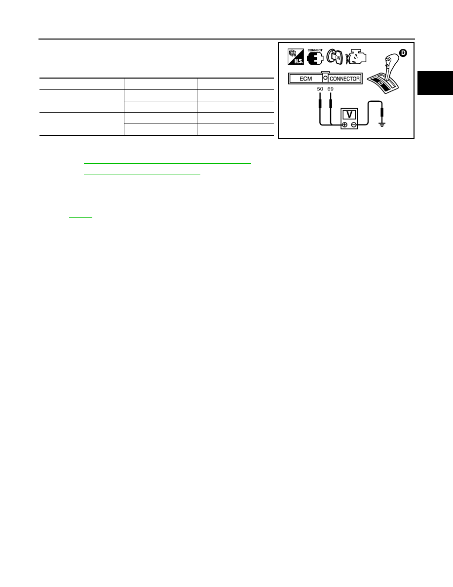
5.
Check voltage between ECM terminals 50 (TP sensor 1 signal),
69 (TP sensor 2 signal) and body ground under the following
conditions.
6.
If NG, replace electric throttle control actuator and go to the next
step.
7.
EC-85, "Throttle Valve Closed Position Learning"
.
8.
EC-85, "Idle Air Volume Learning"
Removal and Installation
INFOID:0000000001326130
ELECTRIC THROTTLE CONTROL ACTUATOR
Terminal
Accelerator pedal
Voltage
50
(Throttle position sensor 1)
Fully released
More than 0.36V
Fully depressed
Less than 4.75V
69
(Throttle position sensor 2)
Fully released
Less than 4.75V
Fully depressed
More than 0.36V
PBIB1608E

EC-308
< SERVICE INFORMATION >
[VQ35DE]
DTC P0300, P0301, P0302, P0303, P0304, P0305, P0306 MULTIPLE CYLINDER
MISFIRE, NO. 1 - 6 CYLINDER MISFIRE
DTC P0300, P0301, P0302, P0303, P0304, P0305, P0306 MULTIPLE CYL-
INDER MISFIRE, NO. 1 - 6 CYLINDER MISFIRE
On Board Diagnosis Logic
INFOID:0000000001326131
When a misfire occurs, engine speed will fluctuate. If the engine speed fluctuates enough to cause the crank-
shaft position (CKP) sensor (POS) signal to vary, ECM can determine that a misfire is occurring.
The misfire detection logic consists of the following two conditions.
1.
One Trip Detection Logic (Three Way Catalyst Damage)
On the 1st trip that a misfire condition occurs that can damage the three way catalyst (TWC) due to over-
heating, the MIL will blink.
When a misfire condition occurs, the ECM monitors the CKP sensor signal every 200 engine revolutions
for a change.
When the misfire condition decreases to a level that will not damage the TWC, the MIL will turn off.
If another misfire condition occurs that can damage the TWC on a second trip, the MIL will blink.
When the misfire condition decreases to a level that will not damage the TWC, the MIL will remain on.
If another misfire condition occurs that can damage the TWC, the MIL will begin to blink again.
2.
Two Trip Detection Logic (Exhaust quality deterioration)
For misfire conditions that will not damage the TWC (but will affect vehicle emissions), the MIL will only
light when the misfire is detected on a second trip. During this condition, the ECM monitors the CKP sen-
sor signal every 1,000 engine revolutions.
A misfire malfunction can be detected on any one cylinder or on multiple cylinders.
DTC Confirmation Procedure
INFOID:0000000001326132
CAUTION:
Always drive vehicle in safe manner according to traffic conditions and obey all traffic laws when driv-
ing.
NOTE:
If DTC Confirmation Procedure has been previously conducted, always turn ignition switch OFF and wait at
least 10 seconds before conducting the next test.
WITH CONSULT-III
1.
Turn ignition switch ON, and select “DATA MONITOR” mode with CONSULT-III.
2.
Start engine and warm it up to normal operating temperature.
3.
Turn ignition switch OFF and wait at least 10 seconds.
4.
Restart engine and let it idle for about 15 minutes.
Sensor
Input Signal to ECM
ECM function
Crankshaft position sensor (POS)
Engine speed
On board diagnosis of misfire
DTC No.
Trouble diagnosis name
DTC detecting condition
Possible cause
P0300
0300
Multiple cylinder misfire
detected
Multiple cylinder misfire.
• Improper spark plug
• Insufficient compression
• Incorrect fuel pressure
• Fuel injector circuit is open or shorted
• Fuel injector
• Intake air leak
• Ignition signal circuit is open or shorted
• Lack of fuel
• Signal plate
• Air fuel ratio (A/F) sensor 1
• Incorrect PCV hose connection
P0301
0301
No.1 cylinder misfire de-
tected
No. 1 cylinder misfires.
P0302
0302
No. 2 cylinder misfire
detected
No. 2 cylinder misfires.
P0303
0303
No. 3 cylinder misfire
detected
No. 3 cylinder misfires.
P0304
0304
No. 4 cylinder misfire
detected
No. 4 cylinder misfires.
P0305
0305
No. 5 cylinder misfire
detected
No. 5 cylinder misfires.
P0306
0306
No. 6 cylinder misfire
detected
No. 6 cylinder misfires.
Нет комментариевНе стесняйтесь поделиться с нами вашим ценным мнением.
Текст