Infiniti FX35 / FX45. Manual — part 9
ACS-30
< SERVICE INFORMATION >
[ICC]
TROUBLE DIAGNOSIS — GENERAL DESCRIPTION
WORK SUPPORT
Cause of Auto-Cancel
Display Item List
NOTE:
Last five cancel (system cancel) causes are displayed.
SELF DIAGNOSTIC RESULT
For details, refer to
ACS-35, "Diagnostic Trouble Code (DTC) Chart"
.
DATA MONITOR
×
: Applicable
Work Support
• Monitors aiming direction to facilitate laser beam aiming operation.
• Indicates causes of automatic cancellation of the ICC system.
Ecu Identification
Displays part number of ICC unit.
Test mode
Function
Operation
Function
CAUSE OF AUTO-CANCEL
Indicates causes of automatic cancellation of the ICC system.
LASER BEAM ADJUST
Outputs laser beam, calculates dislocation of the beam, and indicates adjustment direction.
For details, refer to
Cause of cancellation
Description
OPERATING WIPER
Windshield wipers were operated at HI or LO speed operation.
OPERATING ABS
ABS function was operated.
OPERATING TCS
TCS function was operated.
OPERATING VDC
VDC function was operated.
OPE SW VOLT CIRC
Outside the standard control switch input voltage was detected.
ECM CIRCUIT
ECM did not permit ICC operation.
LASER SUN BEAM
Intense light such as sunlight entered ICC sensor light sensing part.
LASER TEMP
Temperature around ICC sensor became low.
OP SW DOUBLE TOUCH
ICC steering switches were pressed at the same time.
WHL SPD ELEC NOISE
Wheel speed sensor signal caught electromagnetic noise.
VDC/TCS OFF SW
VDC OFF switch was pressed.
WHEEL SPD UNMATCH
Wheel speed became different from AT vehicle speed.
TIRE SLIP
Wheel slipped.
PKB SW ON
Parking brake is applied.
IGN LOW VOLT
Power supply voltage became low.
SNOW MODE SW
Snow mode switch was pressed.
NO RECORD
—
Monitored Item [unit]
ECU INPUT
SIGNALS
MAIN
SIGNALS
SELECTION
FROM
MENU
Description
VHCL SPEED SE
[km/h] or [mph]
×
×
×
Indicates vehicle speed calculated from ICC unit through CAN
communication [ABS actuator and electric unit (control unit)
transmits wheel speed sensor signal through CAN communica-
tion].
SET VHCL SPD
[km/h] or [mph]
×
×
Indicates set vehicle speed memorized in ICC unit.
THRTL OPENING
[%]
×
×
×
Indicates throttle angle read from ICC unit through CAN commu-
nication (ECM transmits throttle angle through CAN communica-
tion).

TROUBLE DIAGNOSIS — GENERAL DESCRIPTION
ACS-31
< SERVICE INFORMATION >
[ICC]
C
D
E
F
G
H
I
J
L
M
A
B
ACS
N
O
P
ENGINE RPM
[rpm]
×
×
Indicates engine speed read from ICC unit through CAN commu-
nication (ECM transmits engine speed through CAN communica-
tion).
DISTANCE ADJ
[ShortMid/Long]
×
×
×
Indicates set distance memorized in ICC unit.
WIPER SW
[Off/Low/High]
×
×
Indicates wiper [OFF/LOW/HIGH] status (BCM transmits front
wiper request signal through CAN communication).
MAIN SW
[On/Off]
×
×
×
Indicates [On/Off] status as judged from ICC steering switch sig-
nal (ECM transmits ICC steering switch signal through CAN com-
munication).
SET/COAST SW
[On/Off]
×
×
×
Indicates [On/Off] status as judged from ICC steering switch sig-
nal (ECM transmits ICC steering switch signal through CAN com-
munication).
CANCEL SW
[On/Off]
×
×
×
Indicates [On/Off] status as judged from ICC steering switch sig-
nal (ECM transmits ICC steering switch signal through CAN com-
munication).
RESUME/ACC SW
[On/Off]
×
×
×
Indicates [On/Off] status as judged from ICC steering switch sig-
nal (ECM transmits ICC steering switch signal through CAN com-
munication).
CRUISE OPE
[On/Off]
×
×
Indicates whether controlling or not (On means “controlling”).
BRAKE SW
[On/Off]
×
×
×
Indicates [On/Off] status as judged from ICC brake switch signal.
STOP LAMP SW
[On/Off]
×
×
×
Indicates [On/Off] status as judged from stop lamp switch signal.
RELEASE SW NO
[On/Off]
×
×
Indicates [On/Off] status as judged from release switch signal.
ON when brake is depressed.
OFF when brake is not depressed.
RELEASE SW NC
[On/Off]
×
×
Indicates [On/Off] status as judged from release switch signal.
ON when brake is not depressed.
OFF when brake is depressed.
IDLE SW
[On/Off]
×
×
Indicates [On/Off] status of idle switch read from ICC unit through
CAN communication (ECM transmits On/Off status through CAN
communication).
GEAR
[1, 2, 3, 4, 5]
×
×
Indicates AT gear position read from ICC unit through CAN com-
munication (TCM transmits gear position through CAN commu-
nication).
BUZZER O/P
[On/Off]
×
Indicates [On/Off] status of ICC warning chime output.
ICC WARNING
×
NOTE:
This item is displayed, but cannot monitor.
VHCL SPD AT
[km/h] or [mph]
×
Indicates vehicle speed calculated from AT vehicle speed sensor
read from ICC unit through CAN communication (TCM transmits
AT vehicle speed sensor signal through CAN communication).
PRESS SENS
[bar]
×
×
×
Indicates brake fluid pressure value calculated from signal volt-
age of pressure sensor.
PRESS SENS 2
×
×
NOTE:
This item is displayed, but cannot monitor.
D RANGE SW
[On/Off]
×
×
Indicates [On/Off] status of “D” position read from ICC unit
through CAN communication (TCM transmits On/Off condition of
“D” position through CAN communication).
A/T OD OFF
[On/Off]
×
Indicates [On/Off] status of OD cancel output under control.
Monitored Item [unit]
ECU INPUT
SIGNALS
MAIN
SIGNALS
SELECTION
FROM
MENU
Description
ACS-32
< SERVICE INFORMATION >
[ICC]
TROUBLE DIAGNOSIS — GENERAL DESCRIPTION
ACTIVE TEST
CAUTION:
• Never perform the active test while driving.
• Active test cannot be started while ICC system warning indicator illuminates.
ICC BUZZER 1
• Touch “ON” and “OFF” to check that ICC warning chime operates as in the following chart.
METER LAMP
• Start engine.
• Touch “ON” and “OFF” to check that ICC system display operates as in the following chart.
STOP LAMP
• Touch “ON” and “OFF” to check that stop lamp operates as in the following chart.
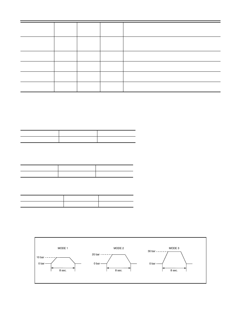
BOOSTER SOL/V 3
• Start engine.
• Touch any of “MODE 1”, “MODE 2”, “MODE 3” to check that following operation condition is caused by oper-
ating monitor and brake pedal.
• “START” is displayed 10 seconds after operation start. (Active test is completed.)
Self-Diagnostic Function
INFOID:0000000001328824
WITH CONSULT-III
NP RANGE SW
[On/Off]
×
×
Indicates PNP switch signal read from ICC unit through CAN
communication (TCM transmits PNP switch signal through CAN
communication).
DISTANCE
×
NOTE:
This item is displayed, but cannot monitor.
RELATIVE SPD
×
NOTE:
This item is displayed, but cannot monitor.
STP LMP DRIVE
[On/Off]
×
×
Indicates [On/Off] status of brake hold relay drive output.
TURN SIGNAL
×
×
NOTE:
This item is displayed, but cannot monitor.
Monitored Item [unit]
ECU INPUT
SIGNALS
MAIN
SIGNALS
SELECTION
FROM
MENU
Description
BUZZER O/P
ON
OFF
Buzzer sound
Beep
Not activated
METER LAMP
ON
OFF
ICC system display
Full illumination
OFF
STP LMP DRIVE
ON
OFF
Stop lamp
Lamp ON
Lamp OFF
PKIA9821E
TROUBLE DIAGNOSIS — GENERAL DESCRIPTION
ACS-33
< SERVICE INFORMATION >
[ICC]
C
D
E
F
G
H
I
J
L
M
A
B
ACS
N
O
P
1.
Go to operation check after asking the customer for symptom information. Refer to
.
2.
Stop vehicle, turn ignition switch OFF, then connect CONSULT-III.
3.
With engine started, check “Self Diagnostic Result” of ICC system.
4.
Self-diagnostic result appears on screen. If “NO DTC ···” is shown, check ICC warning lamp. If any mal-
function is indicated, GO TO step 5.
5.
ACS-35, "Diagnostic Trouble Code (DTC) Chart"
, perform appropriate check, and repair or
replace malfunctioning part as necessary.
6.
Turn ignition switch OFF.
7.
Start the engine and select “Self Diagnostic Result” of ICC system, and erase DTC.
NOTE:
If the memory does not erase, go to 5.
8.
Perform ICC system running test (drive vehicle with ICC system ON), and make sure that ICC warning
lamp does not illuminate.
WITHOUT CONSULT-III
1.
Go to operation check after asking the customer for symptom information. Refer to
.
2.
Stop the vehicle to start the self-diagnosis.
3.
Turn ignition switch OFF.
4.
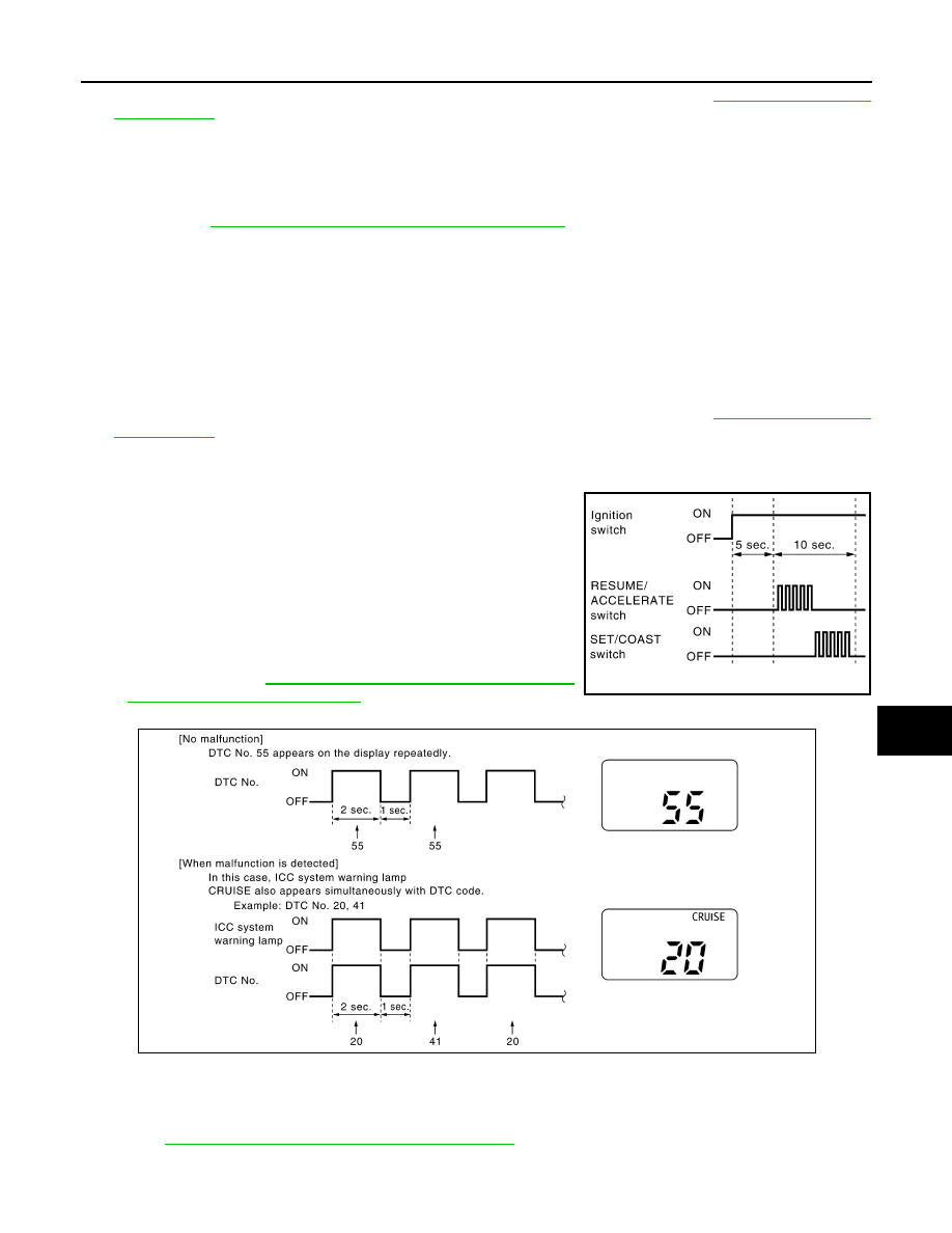
From 5 seconds through 15 seconds after turning ignition switch
ON, press RESUME/ACCELERATE switch 5 times, and SET/
COAST switch 5 times.
NOTE:
• Never start engine.
• Never turn the MAIN switch ON.
• When operation above is not completed from 5 seconds
through 15 seconds, start again from above go to 3.
• If self-diagnosis mode cannot be started after several
attempts, the ICC unit may have had malfunction. Repair or
replace it. Refer to
ACS-59, "SELF-DIAGNOSIS BY ICC SYS-
5.
When self-diagnosis mode is started, DTC are shown on set vehicle speed indicator.
NOTE:
• DTC will disappear after 5 minutes.
• When more than one malfunction is detected, a maximum of 3 code numbers can be stored; the latest
malfunction will be displayed first.
6.
Check
ACS-35, "Diagnostic Trouble Code (DTC) Chart"
, and repair or replace if necessary.
7.
After repair, erase DTC stored in the ICC unit.
PKIA9675E
PKIA9820E
Нет комментариевНе стесняйтесь поделиться с нами вашим ценным мнением.
Текст