Infiniti FX35 / FX45. Manual — part 118
ATC-68
< SERVICE INFORMATION >
TROUBLE DIAGNOSIS
2.
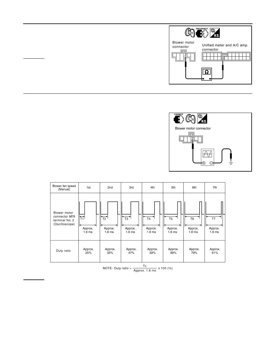
Check continuity between blower motor harness connector M78
terminal 2 and unified meter and A/C amp. harness connector
M57 terminal 53.
OK or NG
OK
>> GO TO 4.
NG
>> Repair harness or connector.
4.
CHECK UNIFIED METER AND A/C AMP. OUTPUT SIGNAL
1.
Reconnect blower motor connector and unified meter and A/C amp. connector.
2.
Turn ignition switch ON.
3.
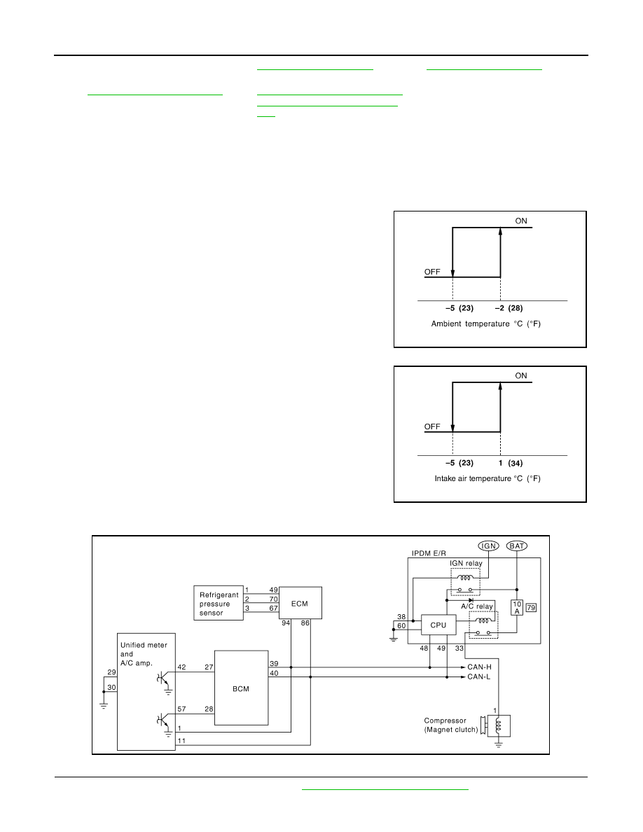
Change the fan speed from Lo to Hi, and check the duty ratios
between blower motor harness connector M78 terminal 2 and
ground using an oscilloscope. Normal terminal 2 drive signal
duty ratios are shown in the table below.
OK or NG
OK
>> Replace blower motor after confirming the fan air flow does not change.
NG
>> Replace unified meter and A/C amp.
COMPONENT INSPECTION
Blower Motor
2 – 53
: Continuity should exist.
RJIA1999E
RJIA2000E
SJIA1802E

TROUBLE DIAGNOSIS
ATC-69
< SERVICE INFORMATION >
C
D
E
F
G
H
I
K
L
M
A
B
ATC
N
O
P
Confirm smooth rotation of the blower motor.
• Ensure that there are no foreign particles inside the blower unit.
Magnet Clutch Circuit
INFOID:0000000001328190
SYMPTOM: Magnet clutch does not engage.
INSPECTION FLOW
RJIA0905E
*1
ATC-94, "Intake Sensor Circuit"
*2
ATC-86, "Ambient Sensor Circuit"
*3
ATC-43, "Self-Diagnosis Function"
see No. 13.
SJIA1590E
ATC-70
< SERVICE INFORMATION >
TROUBLE DIAGNOSIS
SYSTEM DESCRIPTION
Unified meter and A/C amp. controls compressor operation by ambient temperature, intake air temperature
and signal from ECM.
Low Temperature Protection Control
Unified meter and A/C amp. will turn the compressor ON or OFF as determined by a signal detected by ambi-
ent sensor and intake sensor.
When ambient temperature is higher than
−
2
°
C (28
°
F), the compres-
sor turns ON. The compressor turns OFF when ambient temperature
is lower than
−
5
°
C (23
°
F).
When intake air temperature is higher than 1
°
C (34
°
F), the compres-
sor turns ON. The compressor turns OFF when intake air tempera-
ture is lower than
−
5
°
C (23
°
F).
DIAGNOSIS PROCEDURE FOR MAGNET CLUTCH
SYMPTOM: Magnet clutch does not engage when A/C switch is ON.
1.
CHECK AMBIENT SENSOR AND INTAKE SENSOR CIRCUIT
Check ambient sensor and intake sensor. Refer to
ATC-43, "Self-Diagnosis Function"
, see No. 9 and 11.
*4
"DIAGNOSIS PROCEDURE FOR
MAGNET CLUTCH"
*5
ATC-75, "Insufficient Cooling"
*6
*7
ATC-43, "Self-Diagnosis Function"
see No. 4 to 6.
*8
ATC-32, "How to Perform Trouble Di-
agnosis for Quick and Accurate Re-
pair"
RHA094GB
SJIA0267E
SJIA1608E
TROUBLE DIAGNOSIS
ATC-71
< SERVICE INFORMATION >
C
D
E
F
G
H
I
K
L
M
A
B
ATC
N
O
P
OK or NG
OK
>> GO TO 2.
NG
>> • Malfunctioning ambient sensor: Refer to
ATC-86, "Ambient Sensor Circuit"
.
• Malfunctioning intake sensor: Refer to
ATC-94, "Intake Sensor Circuit"
2.
PERFORM IPDM E/R AUTO ACTIVE TEST
Perform “IPDM E/R auto active test”. Refer to
.
Does the magnet clutch operate?
YES
>> •
WITH CONSULT-III: GO TO 5
•
WITHOUT CONSULT-III: GO TO 6.
NO
>> Check 10A fuse (No. 79, located in IPDM E/R). Refer to
PG-23, "IPDM E/R Terminal Arrange-
, and GO TO 3.
3.
CHECK CIRCUIT CONTINUITY BETWEEN IPDM E/R AND COMPRESSOR
1.
Turn ignition switch OFF.
2.
Disconnect IPDM E/R connector and compressor connector.
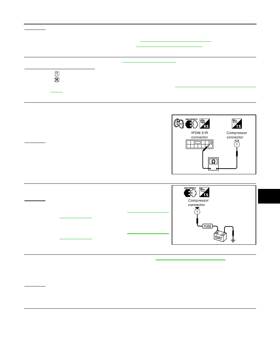
3.
Check continuity between IPDM E/R harness connector E8 ter-
minal 33 and compressor harness connector F2 terminal 1.
OK or NG
OK
>> GO TO 4.
NG
>> Repair harness or connector.
4.
CHECK MAGNET CLUTCH CIRCUIT
Check for operation sound when applying battery voltage direct cur-
rent to terminal.
OK or NG
OK
>> 1.
Replace IPDM E/R.
2.
Go to self-diagnosis procedure
and perform self-diagnosis STEP-4.
Confirm that magnet clutch operation normal.
NG
>> 1.
Replace magnet clutch.
2.
Go to self-diagnosis procedure
and perform self-diagnosis STEP-4.
Confirm that magnet clutch operation normal.
5.
CHECK BCM INPUT (COMPRESSOR ON) SIGNAL
Check compressor ON/OFF signal in “Data monitor”. Refer to
ATC-32, "CONSULT-III Function"
OK or NG
OK
>> GO TO 8.
NG
>> GO TO 6.
6.
CHECK CIRCUIT CONTINUITY BETWEEN BCM AND UNIFIED METER AND A/C AMP.
1.
Turn ignition switch OFF.
2.
Disconnect BCM connector and unified meter and A/C amp. connector.
33 – 1
: Continuity should exist.
RJIA2004E
RJIA2005E
A/C SW ON
: AIR COND SW ON
A/C SW OFF
: AIR COND SW OFF
Нет комментариевНе стесняйтесь поделиться с нами вашим ценным мнением.
Текст