Infiniti FX35 / FX45. Manual — part 296
WARNING CHIME
DI-59
< SERVICE INFORMATION >
C
D
E
F
G
H
I
J
L
M
A
B
DI
N
O
P
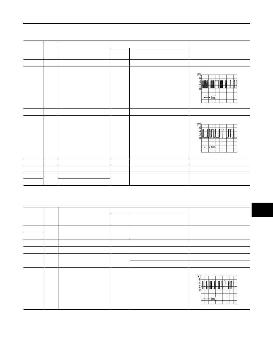
Terminal and Reference Value for Unified Meter and A/C Amp.
INFOID:0000000001328478
Terminal and Reference Value for Combination Meter
INFOID:0000000001328479
Terminal
No.
Wire
color
Item
Measuring condition
Reference value
Ignition
switch
Operation or condition
1
L
CAN-H
OFF
—
—
9
PU
TX communication line (To
combination meter)
ON
—
11
P
CAN-L
OFF
—
—
19
L/B
RX communication line
(From combination meter)
ON
—
21
R/W
Battery power supply
OFF
—
Battery voltage
22
W
Ignition power supply
ON
—
Battery voltage
29
B
Ground (Power)
ON
—
Approx. 0 V
30
Ground
SKIA3362E
SKIA3361E
Terminal
No.
Wire
color
Item
Measuring condition
Reference value
Ignition
switch
Operation or condition
5
B
Ground
ON
—
Approx. 0 V
6
7
G/Y
Ignition power supply
ON
—
Battery voltage
8
R/W
Battery power supply
OFF
—
Battery voltage
9
LG
Seat belt buckle switch (Driv-
er side)
ON
Unfastened (ON)
Approx. 0 V
Fastened (OFF)
Approx. 12 V
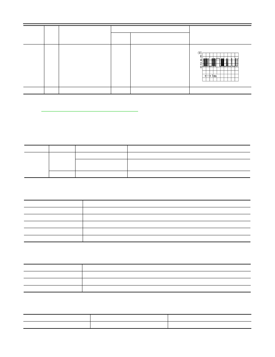
13
L/B
TX communication line (To
unified meter and A/C amp.)
ON
—
SKIA3361E
DI-60
< SERVICE INFORMATION >
WARNING CHIME
CONSULT-III Function (METER/M&A)
INFOID:0000000001328480
DI-27, "CONSULT-III Function (METER/M&A)"
in “UNIFIED METER AND A/C AMP”.
CONSULT-III Function (BCM)
INFOID:0000000001328481
CONSULT-III can display each diagnostic item using the diagnostic test modes shown following.
DIAGNOSIS ITEMS DESCRIPTION
DATA MONITOR
Display Item List
ACTIVE TEST
Display Item List
SELF DIAGNOSTIC RESULT
Display Item List
NOTE:
14
PU
RX communication line
(From unified meter and A/C
amp.)
ON
—
15
B
Ground
ON
—
Approx. 0 V
Terminal
No.
Wire
color
Item
Measuring condition
Reference value
Ignition
switch
Operation or condition
SKIA3362E
System
Test item
Diagnosis mode
Description
BCM
BUZZER
Data Monitor
Displays BCM input data in real time.
Active Test
Operation of electrical loads can be checked by sending driving signal
to them.
BCM
Self Diagnostic Result
BCM checks the conditions and displays memorized error.
Monitored item
Description
IGN ON SW [On/Off]
Indicates [On/Off] condition of ignition switch.
KEY ON SW [On/Off]
Indicates [On/Off] condition of key switch.
DOOR SW-DR [On/Off]
Indicates [On/Off] condition of front door switch (driver side).
LIGHT SW 1ST [On/Off]
Indicates [On/Off] condition of lighting switch.
BUCKLE SW [On/Off]
Indicates [On/Off] condition of seat belt switch (driver side).
Test item
Malfunction is detected when···
LIGHT WARN ALM
This test is able to check light warning chime operation.
IGN KEY WARN ALM
This test is able to check ignition key warning chime operation.
SEAT BELT WARN TEST
This test is able to check seat belt warning chime operation.
Monitored Item
CONSULT-llI display
Description
CAN communication
CAN communication [U1000]
Malfunction is detected in CAN communication.

WARNING CHIME
DI-61
< SERVICE INFORMATION >
C
D
E
F
G
H
I
J
L
M
A
B
DI
N
O
P
If “CAN communication [U1000]” is indicated, after printing the monitor item, go to “LAN system”. Refer to
LAN-43, "CAN System Specification Chart"
Trouble Diagnosis
INFOID:0000000001328482
HOW TO PERFORM TROUBLE DIAGNOSIS
1.
Confirm the symptom or customer complaint.
2.
Understand operation description and function description. Refer to
3.
Perform the preliminary inspection. Refer to "PRELIMINARY INSPECTION".
4.
Referring to trouble diagnosis chart, make sure the cause of the malfunction and repair or replace applica-
ble parts. Refer to
5.
Does the warning chime operate normally? If so, GO TO 6. If not, GO TO 3.
6.
INSPECTION END
PRELIMINARY INSPECTION
1.
CHECK BCM (CONSULT-III)
Perform self-diagnosis of BCM. Refer to
DI-60, "CONSULT-III Function (BCM)"
Self-diagnosis results
No malfunction detected >> GO TO 2.
Malfunction detected >> Check applicable parts, and repair or replace corresponding parts.
2.
CHECK UNIFIED METER AND A/C AMP. (CONSULT-III)
Perform self-diagnosis of unified meter and A/C amp. Refer to
DI-27, "CONSULT-III Function (METER/M&A)"
.
Self-diagnosis results
No malfunction detected >> INSPECTION END
Malfunction detected >> Check applicable parts, and repair or replace corresponding parts.
Symptom Chart
INFOID:0000000001328483
Power Supply and Ground Circuit Inspection
INFOID:0000000001328484
1.
CHECK FUSE AND FUSIBLE LINK
Check for blown BCM fuses and fusible link.
Symptom
Diagnoses/Service procedure
All warning chimes do not activate.
Perform the following inspections.
1.
DI-62, "Combination Meter Buzzer Circuit Inspection"
2.
DI-61, "Power Supply and Ground Circuit Inspection"
.
Replace BCM, found normal function in the above inspections.
Ignition key
warning chime
does not acti-
vate.
Without Intelligent Key.
Perform the following inspections.
1.
DI-63, "Front Door Switch (Driver Side) Signal Inspection"
2.
DI-64, "Key Switch Signal Inspection (Without Intelligent Key)"
Replace BCM, found normal function in the above inspections.
With Intelligent Key, when mechan-
ical key is used.
Perform the following inspections.
1.
DI-63, "Front Door Switch (Driver Side) Signal Inspection"
2.
.
Replace BCM, found normal function in the above inspections.
With Intelligent Key, when Intelli-
gent Key is carried with the driver.
Refer to
BL-106, "Trouble Diagnosis Symptom Chart"
Light warning chime does not activate.
Perform the following inspections.
1.
DI-63, "Front Door Switch (Driver Side) Signal Inspection"
2.
LT-104, "Combination Switch Inspection"
.
Replace BCM, found normal function in the above inspections.
Seat belt warning chime does not activate.
Perform
DI-66, "Seat Belt Buckle Switch (Driver Side) Signal Inspection"
.
Replace BCM, found normal function in the above inspection.
DI-62
< SERVICE INFORMATION >
WARNING CHIME
OK or NG
OK
>> GO TO 2.
NG
>> Be sure to eliminate cause of malfunction before installing new fuse or fusible link. Refer to
.
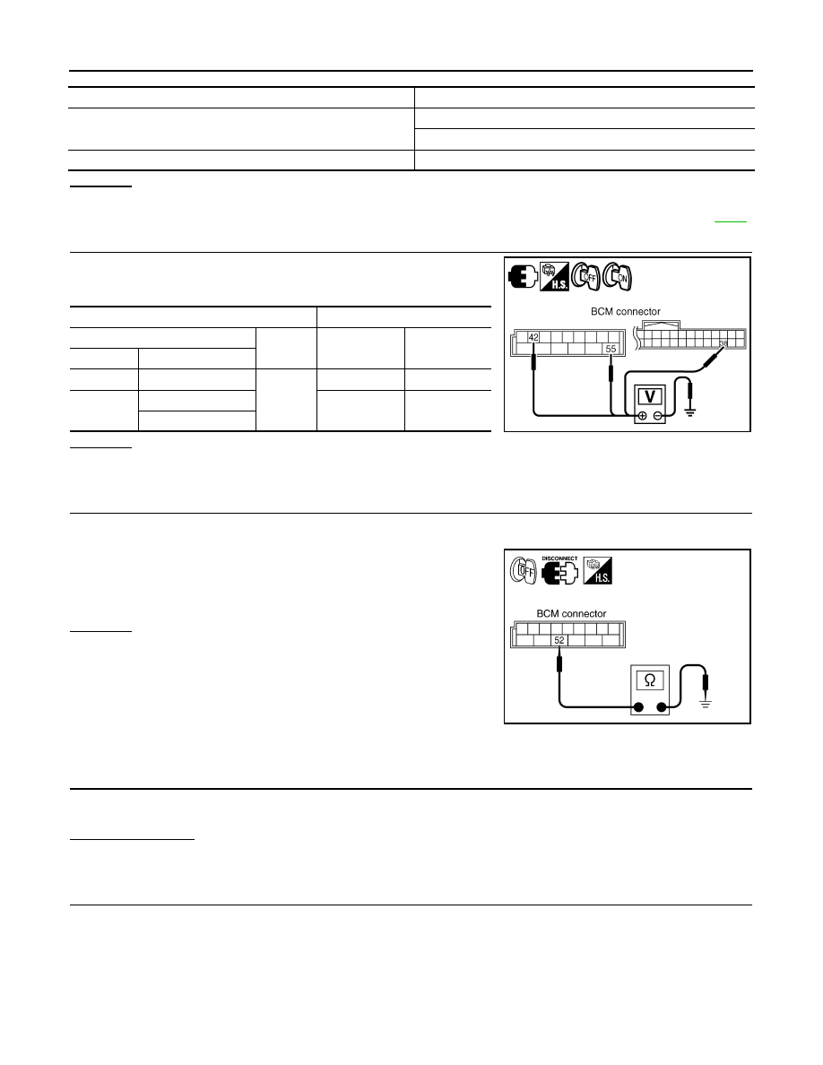
2.
CHECK POWER SUPPLY CIRCUIT
Check voltage between BCM harness connector terminals and
ground.
OK or NG
OK
>> GO TO 3.
NG
>> Check harness between BCM and fuse.
3.
CHECK GROUND CIRCUIT
1.
Turn ignition switch OFF.
2.
Disconnect BCM connector.
3.
Check continuity between BCM harness connector M35 terminal
52 and ground.
OK or NG
OK
>> INSPECTION END
NG
>> Repair harness or connector.
Combination Meter Buzzer Circuit Inspection
INFOID:0000000001328485
1.
CHECK OPERATION OF COMBINATION METER BUZZER
1.
Select “BUZZER” of “BCM” on CONSULT-III.
2.
Perform “LIGHT WARN ALM”, “IGN KEY WARN ALM” or “SEAT BELT WARN TEST” of “Active Test”.
Does chime sound?
YES
>> GO TO 4.
NO
>> GO TO 2.
2.
CHECK UNIFIED METER AND A/C AMP. INPUT SIGNAL
1.
Select “METER/M&A” on CONSULT-III.
2.
Operate switches to meet the requirements to sound warning chime with “BUZZER” of “Data Monitor” and
check operation status.
Power source
Fuse and fusible link No.
Battery power supply
M
22
Ignition power supply
1
Terminals
Ignition switch position
(+)
(–)
OFF
ON
Connector
Terminal
M34
38
Ground
0 V
Battery voltage
M35
42
Battery voltage
Battery voltage
55
PKIB3988E
52 – Ground
: Continuity should exist.
PKIB5011E
“BUZZER”
Нет комментариевНе стесняйтесь поделиться с нами вашим ценным мнением.
Текст