Infiniti FX35 / FX45. Manual — part 583
DTC P2101 ELECTRIC THROTTLE CONTROL FUNCTION
EC-1093
< SERVICE INFORMATION >
[VK45DE]
C
D
E
F
G
H
I
J
K
L
M
A
EC
N
P
O
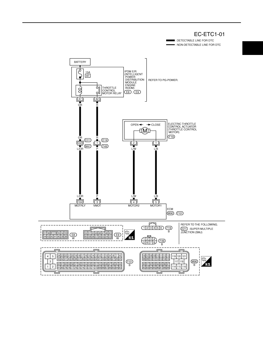
Wiring Diagram
INFOID:0000000001326985
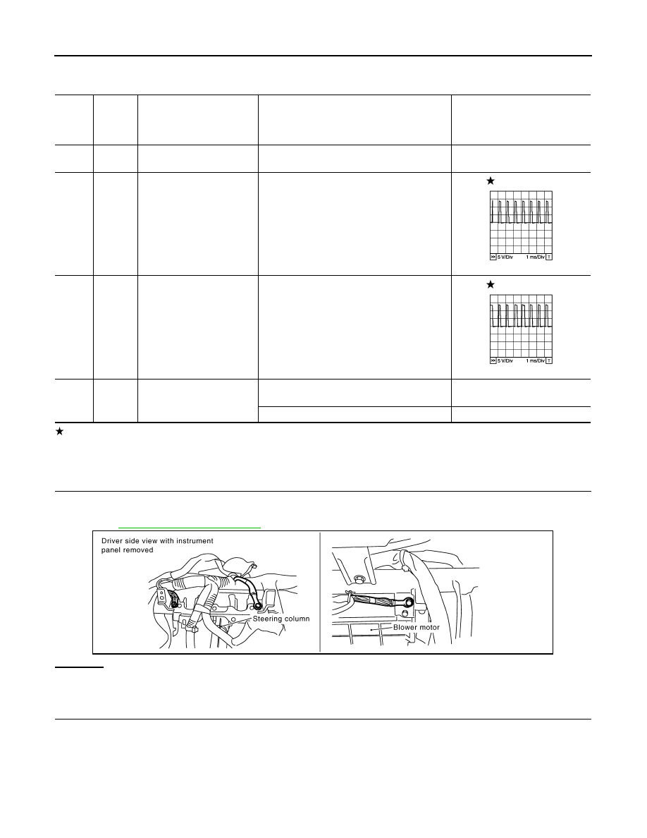
Specification data are reference values and are measured between each terminal and ground.
Pulse signal is measured by CONSULT-III.
CAUTION:
TBWM1344E
EC-1094
< SERVICE INFORMATION >
[VK45DE]
DTC P2101 ELECTRIC THROTTLE CONTROL FUNCTION
Do not use ECM ground terminals when measuring input/output voltage. Doing so may result in dam-
age to the ECM's transistor. Use a ground other than ECM terminals, such as the ground.
: Average voltage for pulse signal (Actual pulse signal can be confirmed by oscilloscope.)
Diagnosis Procedure
INFOID:0000000001326986
1.
CHECK GROUND CONNECTIONS
1.
Turn ignition switch OFF.
2.
Loosen and retighten three ground screws on the body.
Refer to
OK or NG
OK
>> GO TO 2.
NG
>> Repair or replace ground connections.
2.
CHECK THROTTLE CONTROL MOTOR RELAY INPUT SIGNAL CIRCUIT-I
TER-
MI-
NAL
NO.
WIRE
COLOR
ITEM
CONDITION
DATA (DC Voltage)
3
P
Throttle control motor relay
power supply
[Ignition switch: ON]
BATTERY VOLTAGE
(11 - 14V)
4
L/W
Throttle control motor
(Close)
[Ignition switch: ON]
• Engine stopped
• Selector lever: D
• Accelerator pedal: Fully released
0 - 14V
5
L/B
Throttle control motor
(Open)
[Ignition switch: ON]
• Engine stopped
• Selector lever: D
• Accelerator pedal: Fully depressed
0 - 14V
104
L/OR
Throttle control motor relay
[Ignition switch: OFF]
BATTERY VOLTAGE
(11 - 14V)
[Ignition switch: ON]
0 - 1.0V
PBIB1104E
PBIB1105E
PBIB2195E
DTC P2101 ELECTRIC THROTTLE CONTROL FUNCTION
EC-1095
< SERVICE INFORMATION >
[VK45DE]
C
D
E
F
G
H
I
J
K
L
M
A
EC
N
P
O
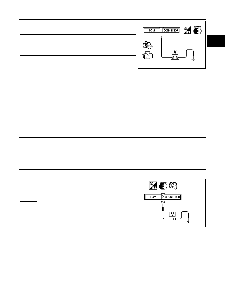
Check voltage between ECM terminal 3 and ground under the fol-
lowing conditions with CONSULT-III or tester.
OK or NG
OK
>> GO TO 10.
NG
>> GO TO 3.
3.
CHECK THROTTLE CONTROL MOTOR RELAY INPUT SIGNAL CIRCUIT-II
1.
Turn ignition switch OFF.
2.
Disconnect ECM harness connector.
3.
Disconnect IPDM E/R harness connector E8.
4.
Check harness continuity between ECM terminal 3 and IPDM E/R terminal 42.
Refer to Wiring Diagram.
5.
Also check harness for short to ground and short to power.
OK or NG
OK
>> GO TO 5.
NG
>> GO TO 4.
4.
DETECT MALFUNCTIONING PART
Check the following.
• Harness connectors E19, F49
• Harness for open or short between ECM and IPDM E/R
>> Repair open circuit or short to ground or short to power in harness or connectors.
5.
CHECK THROTTLE CONTROL MOTOR RELAY POWER SUPPLY CIRCUIT-I
1.
Reconnect all harness connectors disconnected.
2.
Turn ignition switch OFF.
3.
Check voltage between ECM terminal 104 and ground with
CONSULT-III or tester.
OK or NG
OK
>> GO TO 9.
NG
>> GO TO 6.
6.
CHECK THROTTLE CONTROL MOTOR RELAY POWER SUPPLY CIRCUIT-II
1.
Disconnect ECM harness connector.
2.
Disconnect IPDM E/R harness connector E9.
3.
Check harness continuity between ECM terminal 104 and IPDM E/R terminal 47.
Refer to Wiring Diagram.
4.
Also check harness for short to ground and short to power.
OK or NG
OK
>> GO TO 8.
Ignition switch
Voltage
OFF
Approximately 0V
ON
Battery voltage
(11 - 14V)
MBIB0028E
Continuity should exist.
Voltage: Battery voltage
PBIB1171E
Continuity should exist.
EC-1096
< SERVICE INFORMATION >
[VK45DE]
DTC P2101 ELECTRIC THROTTLE CONTROL FUNCTION
NG
>> GO TO 7.
7.
DETECT MALFUNCTIONING PART
Check the following.
• Harness connectors E211, M41
• Harness for open or short between ECM and IPDM E/R
>> Repair open circuit or short to ground or short to power in harness or connectors.
8.
CHECK FUSE
1.
Disconnect 15A fuse.
2.
Check 15A fuse for blown.
OK or NG
OK
>> GO TO 9.
NG
>> Replace 15A fuse.
9.
CHECK INTERMITTENT INCIDENT
OK or NG
OK
>> Replace IPDM E/R. Refer to
.
NG
>> Repair or replace harness or connectors.
10.
CHECK THROTTLE CONTROL MOTOR OUTPUT SIGNAL CIRCUIT FOR OPEN OR SHORT
1.
Turn ignition switch OFF.
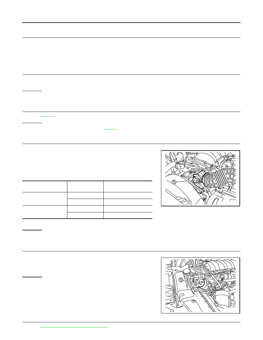
2.
Disconnect electric throttle control actuator (1) harness connec-
tor.
3.
Disconnect ECM harness connector.
4.
Check harness continuity between the following terminals.
Refer to Wiring Diagram.
5.
Also check harness for short to ground and short to power.
OK or NG
OK
>> GO TO 11.
NG
>> Repair or replace.
11.
CHECK ELECTRIC THROTTLE CONTROL ACTUATOR VISUALLY
1.
Remove the intake air duct.
2.
Check if foreign matter is caught between the throttle valve (1)
and the housing.
-
Illustration shows the view with intake air duct removed.
OK or NG
OK
>> GO TO 12.
NG
>> Remove the foreign matter and clean the electric throttle
control actuator inside.
12.
CHECK THROTTLE CONTROL MOTOR
EC-1097, "Component Inspection"
.
Electric throttle control
actuator terminal
ECM terminal
Continuity
1
5
Should exist
4
Should not exist
2
5
Should not exist
4
Should exist
PBIB3232E
PBIB3247E
Нет комментариевНе стесняйтесь поделиться с нами вашим ценным мнением.
Текст