Infiniti FX35 / FX45. Manual — part 714
TRANSVERSE LINK
FSU-13
< SERVICE INFORMATION >
C
D
F
G
H
I
J
K
L
M
A
B
FSU
N
O
P
TRANSVERSE LINK
Removal and Installation
INFOID:0000000001327542
REMOVAL
1.
Remove tire from vehicle with power tool.
2.
Remove undercover with power tool.
3.
Remove front cross bar.
4.
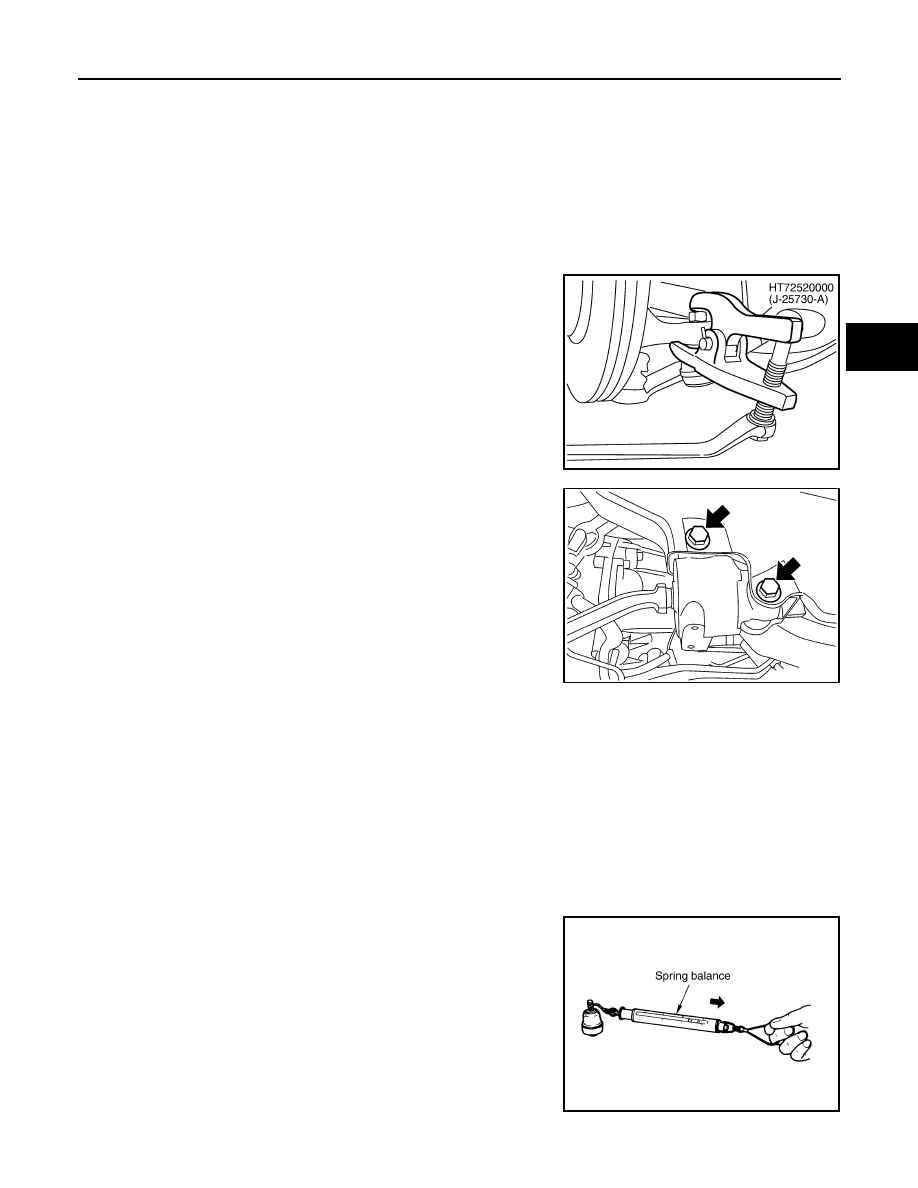
Remove cotter pin at transverse link, then loosen mounting nut.
5.
Use a ball joint remover (SST) to remove transverse link from
steering knuckle. Be careful not to damage ball joint boot.
CAUTION:
Tighten temporarily mounting nut to prevent damage to
threads and to prevent ball joint remover (SST) from com-
ing off.
6.
Remove mounting bolts which are at the back of transverse link
(mounting part with body) with power tool, separate transverse
link.
7.
Remove mounting bolts which are at the front of transverse link
(mounting part with front suspension member) with power tool,
separate transverse link.
8.
Remove transverse link from vehicle.
INSPECTION AFTER REMOVAL
Visual Inspection
• Check transverse link and bushing for deformation, cracks, or damage. If any non-standard condition is
found, replace it.
• Check boot of ball joint for cracks, or other damage, and also for grease leakage. If any non-standard condi-
tion is found, replace it.
Ball Joint Inspection
Manually move ball stud to confirm it moves smoothly with no binding.
Swing Torque Inspection
NOTE:
Before measurement, move ball joint at least ten times by hand to check for smooth movement.
• Hook spring balance at ball stud. Confirm spring balance measure-
ment value is within the specifications when ball stud begins mov-
ing.
• If it is outside the specified range, replace transverse link assem-
bly.
Rotating Torque Inspection
PEIA0109E
SEIA0331E
Swing torque:
Less than 0.5
−
4.9 N·m (0.06
−
0.49 kg-m, 5
−
43 in-lb)
Measure value of spring scale:
Less than 0.5
−
4.9 N·m (0.06
−
0.49 kg-m, 5
−
43 in-lb)
SEIA0523E
FSU-14
< SERVICE INFORMATION >
TRANSVERSE LINK
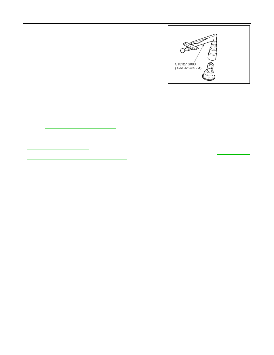
• Attach mounting nut to ball stud. Check that rotating torque is
within the specifications with a preload gauge (SST).
• If it is outside the specified range, replace transverse link assem-
bly.
Axial End Play Inspection
• Move tip of ball joint in axial direction to check for looseness.
• If it is outside the specified range, replace transverse link assembly.
INSTALLATION
• Refer to
FSU-6, "Removal and Installation"
for tightening torque. Install in the reverse order of removal.
NOTE:
Refer to component parts location and do not reuse non-reusable parts.
• After removing/installing or replacing suspension components, check wheel alignment. Refer to
• After adjusting wheel alignment, adjust neutral position of steering angle sensor. Refer to
ment of Steering Angle Sensor Neutral Position"
Rotating Torque:
Less than 0.5
−
4.9 N·m (0.06
−
0.49 kg-m, 5
−
43 in-lb)
SDIA1150E
Axial end play
: 0.1 mm (0.004 in)
STABILIZER BAR
FSU-15
< SERVICE INFORMATION >
C
D
F
G
H
I
J
K
L
M
A
B
FSU
N
O
P
STABILIZER BAR
Removal and Installation
INFOID:0000000001327543
REMOVAL
1.
Remove tires from vehicle with power tool.
2.
Remove undercover with power tool.
3.
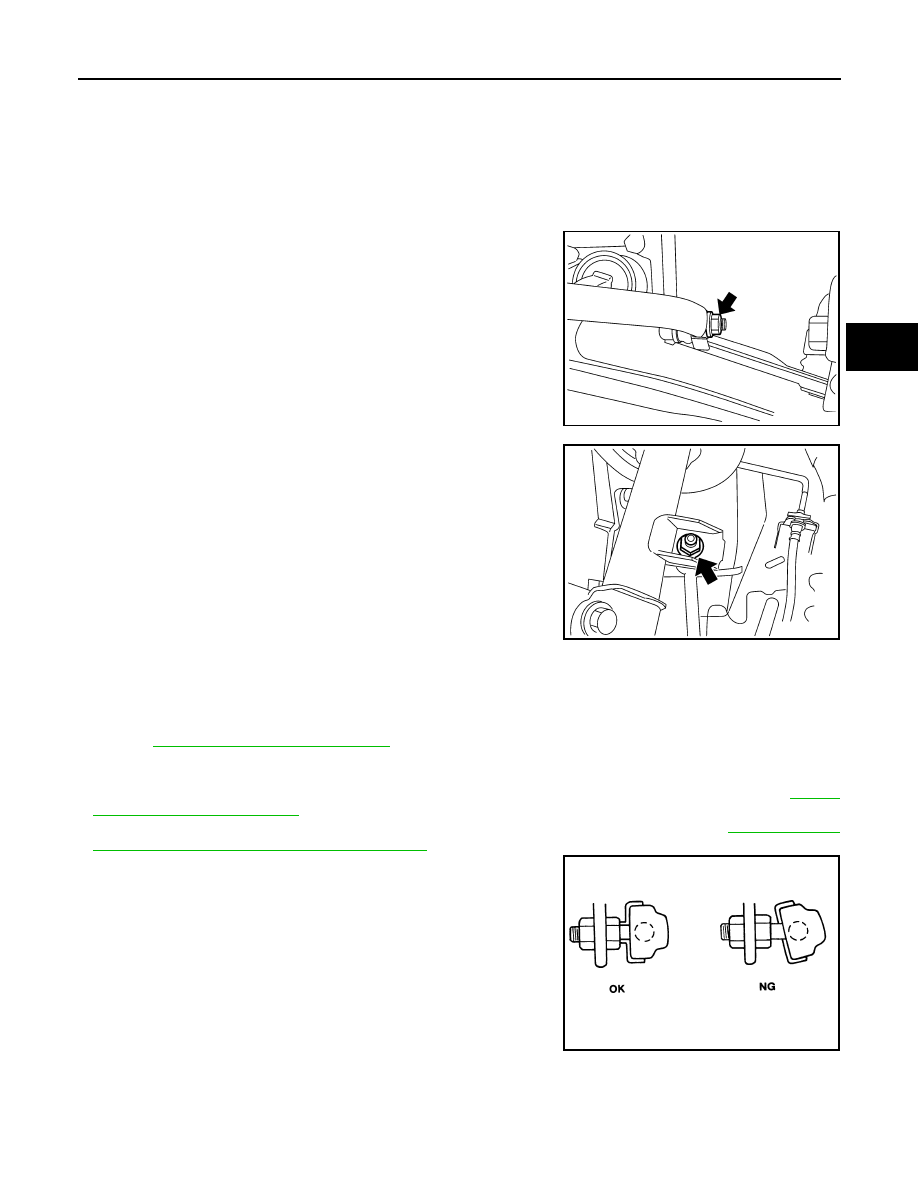
Remove stabilizer connecting rod lower nut with power tool, sep-
arate stabilizer bar and stabilizer connecting rod.
4.
Remove stabilizer clamp mounting bolts and nuts with power
tool.
5.
Remove stabilizer bar, stabilizer clamp, stabilizer bushing from
vehicle.
6.
Remove stabilizer connecting rod upper nut with power tool,
separate stabilizer connecting rod and strut.
INSPECTION AFTER REMOVAL
Check stabilizer bar, stabilizer connecting rod, stabilizer bushing and stabilizer clamp deformation, cracks and
damage, and replace if necessary.
INSTALLATION
• Refer to
FSU-6, "Removal and Installation"
for tightening torque. Install in the reverse order of removal.
NOTE:
Refer to component parts location and do not reuse non-reusable parts.
• After removing/installing or replacing suspension components, check wheel alignment. Refer to
• After adjusting wheel alignment, adjust neutral position of steering angle sensor. Refer to
ment of Steering Angle Sensor Neutral Position"
• Stabilizer bar uses pillow ball type connecting rod. Position ball
joint with case on pillow ball head parallel to stabilizer bar.
SEIA0335E
SEIA0330E
SFA449BB
FSU-16
< SERVICE INFORMATION >
FRONT SUSPENSION MEMBER
FRONT SUSPENSION MEMBER
Removal and Installation
INFOID:0000000001327544
REMOVAL
1.
Set engine slinger to engine, then suspend an engine.
2.
Remove tires from vehicle with power tool.
3.
Remove undercover with power tool.
4.
Remove front cross bar.
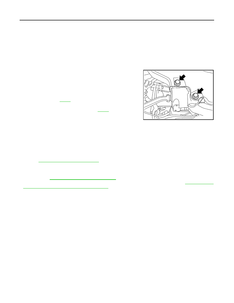
5.
Remove mounting bolts which are at the back of transverse link
(mounting part with body) with power tool, separate transverse
link.
6.
Remove mounting bolts which are at the front of transverse link
with power tool, separate transverse link.
7.
Remove steering hydraulic piping bracket from front suspension
member. Refer to
.
8.
Remove mounting bolts of steering gear with power tool, then
hang steering gear on vehicle. Refer to
9.
Remove stabilizer bar from front suspension member and stabi-
lizer connecting rod lower side with power tool.
10. Remove mounting nuts between engine mounting insulator and front suspension member.
11. Remove mounting nuts between front suspension member and body with power tool.
12. Move jack down slowly to remove front suspension member from vehicle.
INSPECTION AFTER REMOVAL
Check front suspension member for deformation, cracks, or any other damage. Replace if necessary.
INSTALLATION
• Refer to
FSU-6, "Removal and Installation"
for tightening torque. Install in the reverse order of removal.
NOTE:
Refer to component parts location and do not reuse non-reusable parts.
• After removing/installing or replacing suspension components and steering components, check wheel align-
ment. Refer to
FSU-5, "Wheel Alignment Inspection"
• After adjusting wheel alignment, adjust neutral position of steering angle sensor. Refer to
ment of Steering Angle Sensor Neutral Position"
SEIA0331E
Нет комментариевНе стесняйтесь поделиться с нами вашим ценным мнением.
Текст