Infiniti FX35 / FX45. Manual — part 404

DTC P0452 EVAP CONTROL SYSTEM PRESSURE SENSOR
EC-377
< SERVICE INFORMATION >
[VQ35DE]
C
D
E
F
G
H
I
J
K
L
M
A
EC
N
P
O
Wiring Diagram
INFOID:0000000001326209
Specification data are reference values and are measured between each terminal and ground.
CAUTION:
Do not use ECM ground terminals when measuring input/output voltage. Doing so may result in dam-
age to the ECM's transistor. Use a ground other than ECM terminals, such as the ground.
TBWM1392E
EC-378
< SERVICE INFORMATION >
[VQ35DE]
DTC P0452 EVAP CONTROL SYSTEM PRESSURE SENSOR
Diagnosis Procedure
INFOID:0000000001326210
1.
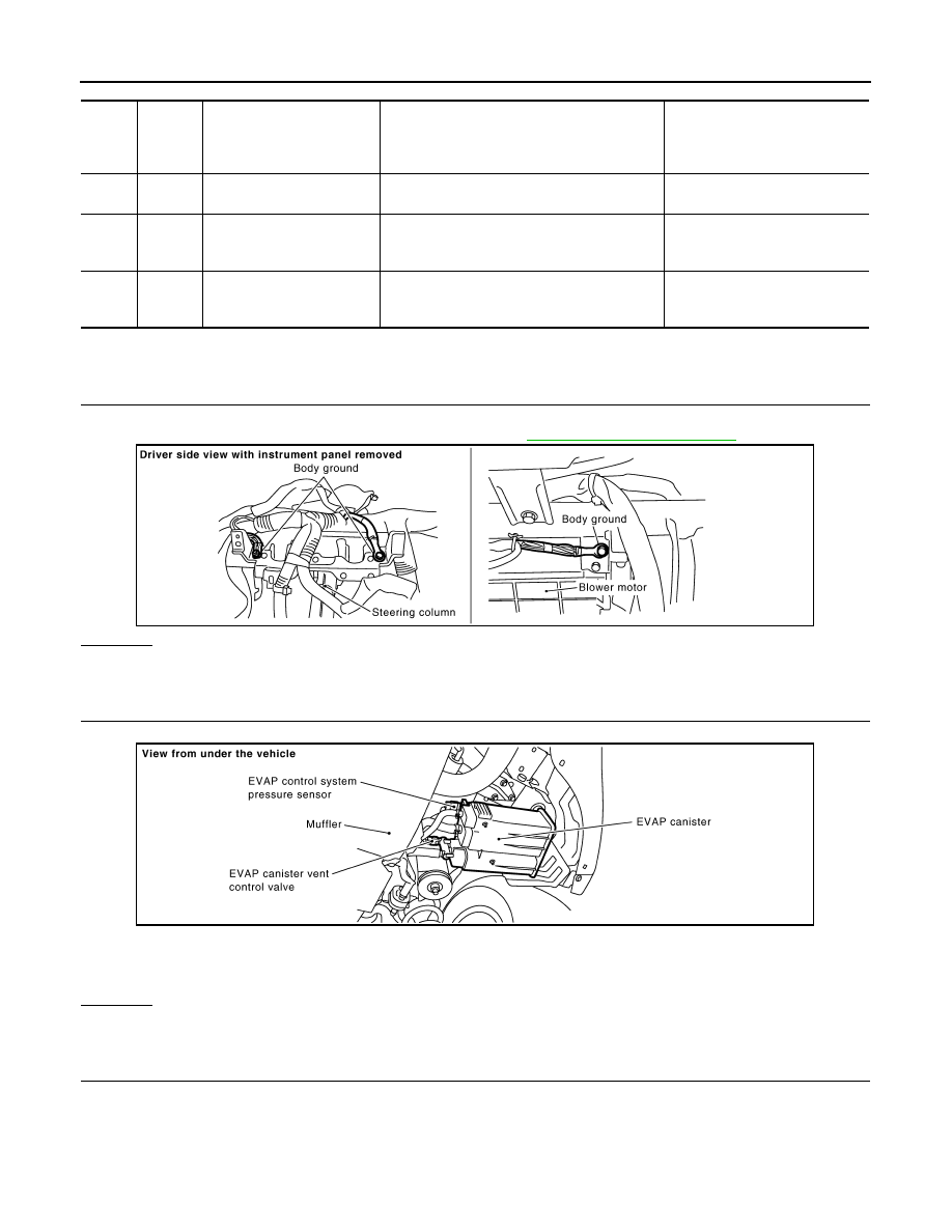
CHECK GROUND CONNECTIONS
1.
Turn ignition switch OFF.
2.
Loosen and retighten ground screw on the body. Refer to
OK or NG
OK
>> GO TO 2.
NG
>> Repair or replace ground connections.
2.
CHECK CONNECTOR
1.
Disconnect EVAP control system pressure sensor harness connector.
2.
Check sensor harness connector for water.
OK or NG
OK
>> GO TO 3.
NG
>> Repair or replace harness connector.
3.
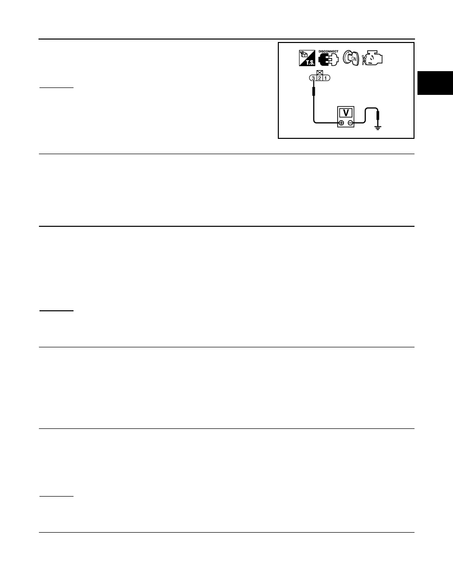
CHECK EVAP CONTROL SYSTEM PRESSURE SENSOR POWER SUPPLY CIRCUIT
1.
Turn ignition switch ON.
TER-
MI-
NAL
NO.
WIRE
COLOR
ITEM
CONDITION
DATA (DC Voltage)
32
OR
EVAP control system pres-
sure sensor
[Ignition switch: ON]
Approximately 1.8 - 4.8V
48
LG
Sensor power supply
(EVAP control system pres-
sure sensor)
[Ignition switch: ON]
Approximately 5V
67
B/W
Sensor ground
[Engine is running]
• Warm-up condition
• Idle speed
Approximately 0V
PBIB2625E
Water should not exist.
PBIB1611E
DTC P0452 EVAP CONTROL SYSTEM PRESSURE SENSOR
EC-379
< SERVICE INFORMATION >
[VQ35DE]
C
D
E
F
G
H
I
J
K
L
M
A
EC
N
P
O
2.
Check voltage between EVAP control system pressure sensor
terminal 3 and ground with CONSULT-III or tester.
OK or NG
OK
>> GO TO 5.
NG
>> GO TO 4.
4.
DETECT MALFUNCTIONING PART
Check the following.
• Harness connectors B201, M81
• Harness connectors M82, F102
• Harness for open or short between EVAP control system pressure sensor and ECM
>> Repair open circuit or short to ground or short to power in harness or connectors.
5.
CHECK EVAP CONTROL SYSTEM PRESSURE SENSOR GROUND CIRCUIT FOR OPEN AND SHORT
1.
Turn ignition switch OFF.
2.
Disconnect ECM harness connector.
3.
Check harness continuity between EVAP control system pressure sensor terminal 1 and ECM terminal
67.
Refer to Wiring Diagram.
4.
Also check harness for short to ground and short to power.
OK or NG
OK
>> GO TO 7.
NG
>> GO TO 6.
6.
DETECT MALFUNCTIONING PART
Check the following.
• Harness connectors B201, M81
• Harness connectors M82, F102
• Harness for open or short between EVAP control system pressure sensor and ECM
>> Repair open circuit or short to ground or short to power in harness or connectors.
7.
CHECK EVAP CONTROL SYSTEM PRESSURE SENSOR INPUT SIGNAL CIRCUIT FOR OPEN AND
SHORT
1.
Check harness continuity between ECM terminal 32 and EVAP control system pressure sensor terminal
2.
Refer to Wiring Diagram.
2.
Also check harness for short to ground and short to power.
OK or NG
OK
>> GO TO 9.
NG
>> GO TO 8.
8.
DETECT MALFUNCTIONING PART
Check the following.
• Harness connectors B201, M81
• Harness connectors M82, F102
Voltage: Approximately 5V
PBIB0138E
Continuity should exist.
Continuity should exist.
EC-380
< SERVICE INFORMATION >
[VQ35DE]
DTC P0452 EVAP CONTROL SYSTEM PRESSURE SENSOR
• Harness for open or short between EVAP control system pressure sensor and ECM
>> Repair open circuit or short to ground or short to power in harness or connectors.
9.
CHECK EVAP CONTROL SYSTEM PRESSURE SENSOR
EC-380, "Component Inspection"
OK or NG
OK
>> GO TO 10.
NG
>> Replace EVAP control system pressure sensor.
10.
CHECK INTERMITTENT INCIDENT
>> INSPECTION END
Component Inspection
INFOID:0000000001326211
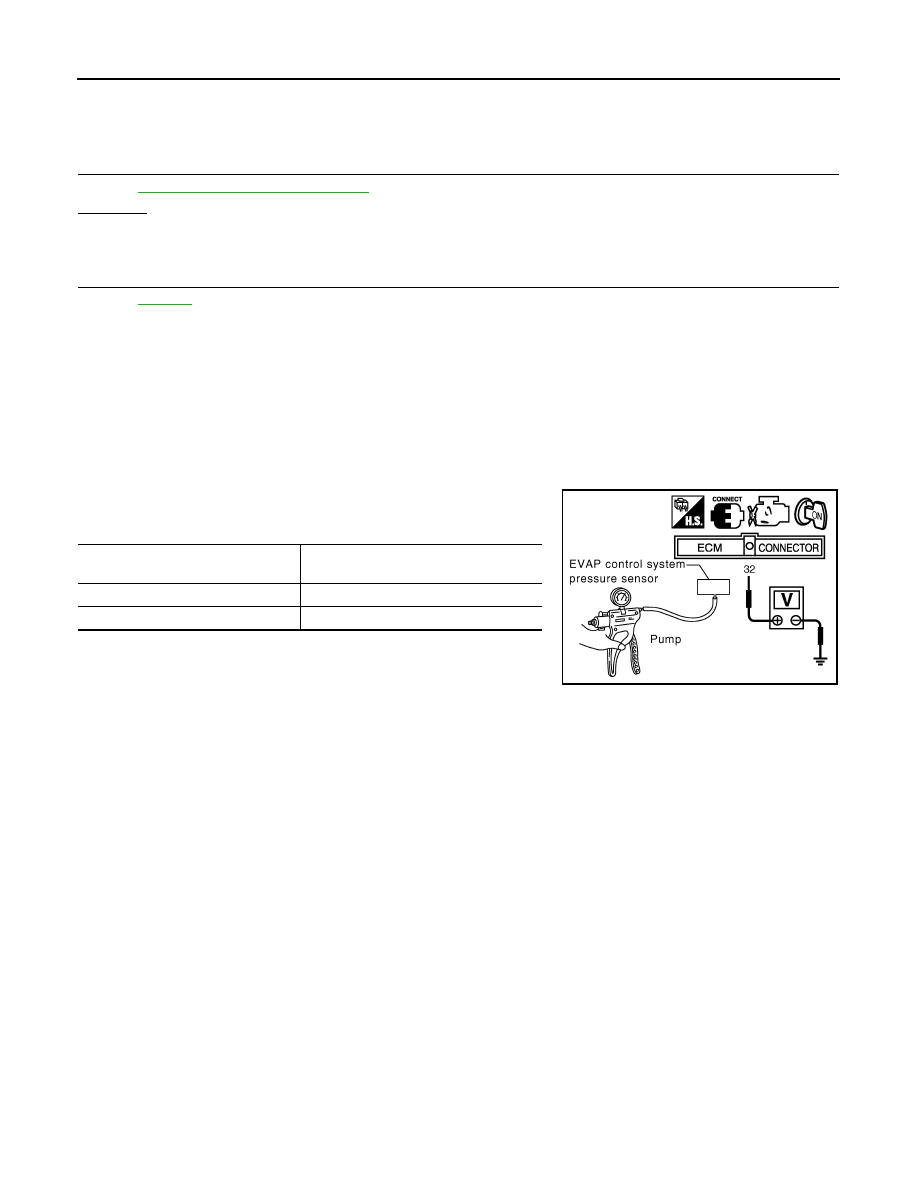
EVAP CONTROL SYSTEM PRESSURE SENSOR
1.
Remove EVAP control system pressure sensor with its harness connector connected from EVAP canister.
Always replace O-ring with a new one.
2.
Install a vacuum pump to EVAP control system pressure sensor.
3.
Turn ignition switch ON and check output voltage between ECM
terminal 32 and ground under the following conditions.
CAUTION:
• Always calibrate the vacuum pump gauge when using it.
• Do not apply below -93.3 kPa (-700 mmHg, -27.56 inHg) or
pressure over 101.3 kPa (760 mmHg, 29.92 inHg).
4.
If NG, replace EVAP control system pressure sensor.
Applied vacuum kPa
(mmHg, inHg)
Voltage V
Not applied
1.8 - 4.8
-26.7 (-200, -7.87)
2.1 to 2.5V lower than above value
PBIB1173E
Нет комментариевНе стесняйтесь поделиться с нами вашим ценным мнением.
Текст