Infiniti FX35 / FX45. Manual — part 299

LANE DEPARTURE WARNING SYSTEM
DI-71
< SERVICE INFORMATION >
C
D
E
F
G
H
I
J
L
M
A
B
DI
N
O
P
NOTE:
*: This indicates in a few seconds for the system check during ignition switch ON.
POWER SUPPLY AND GROUND CIRCUIT
With the ignition switch in the ON or START position, power is supplied
• through 10A fuse [No. 12, located in the fuse block (J/B)]
• to LDW camera unit terminal 1.
Ground is supplied
• to LDW camera unit terminals 6 and 12
• through grounds M45, M85 and M35.
Action Test
INFOID:0000000001328494
LDW SYSTEM RUNNING TEST
WARNING:
• Be careful when performing road test.
• Understand “Precautions” and “System Description” well before the road test. Refer to
caution for Lane Departure Warning (LDW) system"
and
.
Function Check
Check the LDW system operation according to the condition that the warning function works. Refer to
Camera Aiming Adjustment
INFOID:0000000001328495
OUTLINE
Adjust the camera aiming every time the LDW camera unit is removed or installed.
CAUTION:
• Place the vehicle on the level ground when the camera aiming adjustment is operated.
• Follow the CONSULT-III when adjusting the camera aiming. (Camera aiming adjustment cannot be
operated without CONSULT-III.)
PREPARATION
• Keep all tires inflated to correct pressures. Adjust the tire pressure to the specified pressure value.
• There is no-load in vehicle. Check if coolant, engine oil are filled up to correct level and fuel tank is full.
• Shift the gear into “P” position and release the parking brake.
• Clean the windshield.
NOTE:
Do not place anything reflective on the upper surface of instrument panel.
TARGET SETTING
Preparation Aiming Adjustment Jig
Component
Description
LDW camera unit
Detects the lane marker by the built-in camera, gives judgement for the warning according to the result
of detection and signals from each unit, and transmits the operation signal to LDW chime and LDW
indicator lamp.
LDW switch
• Selects ON/OFF of the system.
• Indicates ON/OFF of the signal with LDW system ON indicator.
LDW chime
Gives a warning chime according to the direction from LDW camera unit.
LDW indicator lamp
Installed in combination meter, and indicates the system condition.
• Blinks when LDW system is functioning to alert the driver.
• Stays on when LDW system is malfunctioning.
*
BCM
Transmits turn indicator signal to LDW camera unit with CAN communication signal.
ABS actuator and electric unit
(control unit)
Transmits vehicle speed signal to LDW camera unit with CAN communication signal.
TCM
Transmits vehicle speed signal to LDW camera unit with CAN communication signal. (For detecting
incorrect speed.)
DI-72
< SERVICE INFORMATION >
LANE DEPARTURE WARNING SYSTEM
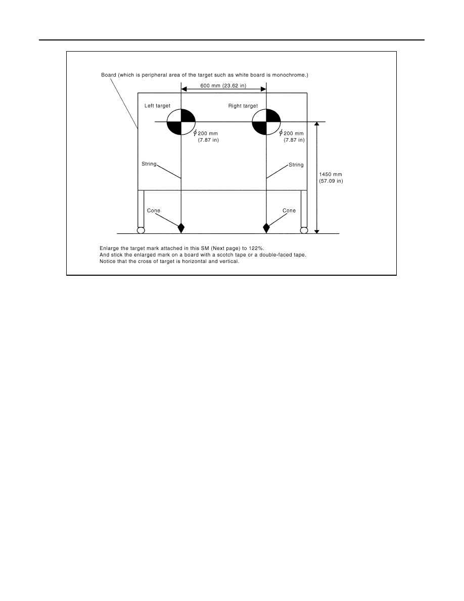
For aiming adjustment, prepare the following jigs and targets.
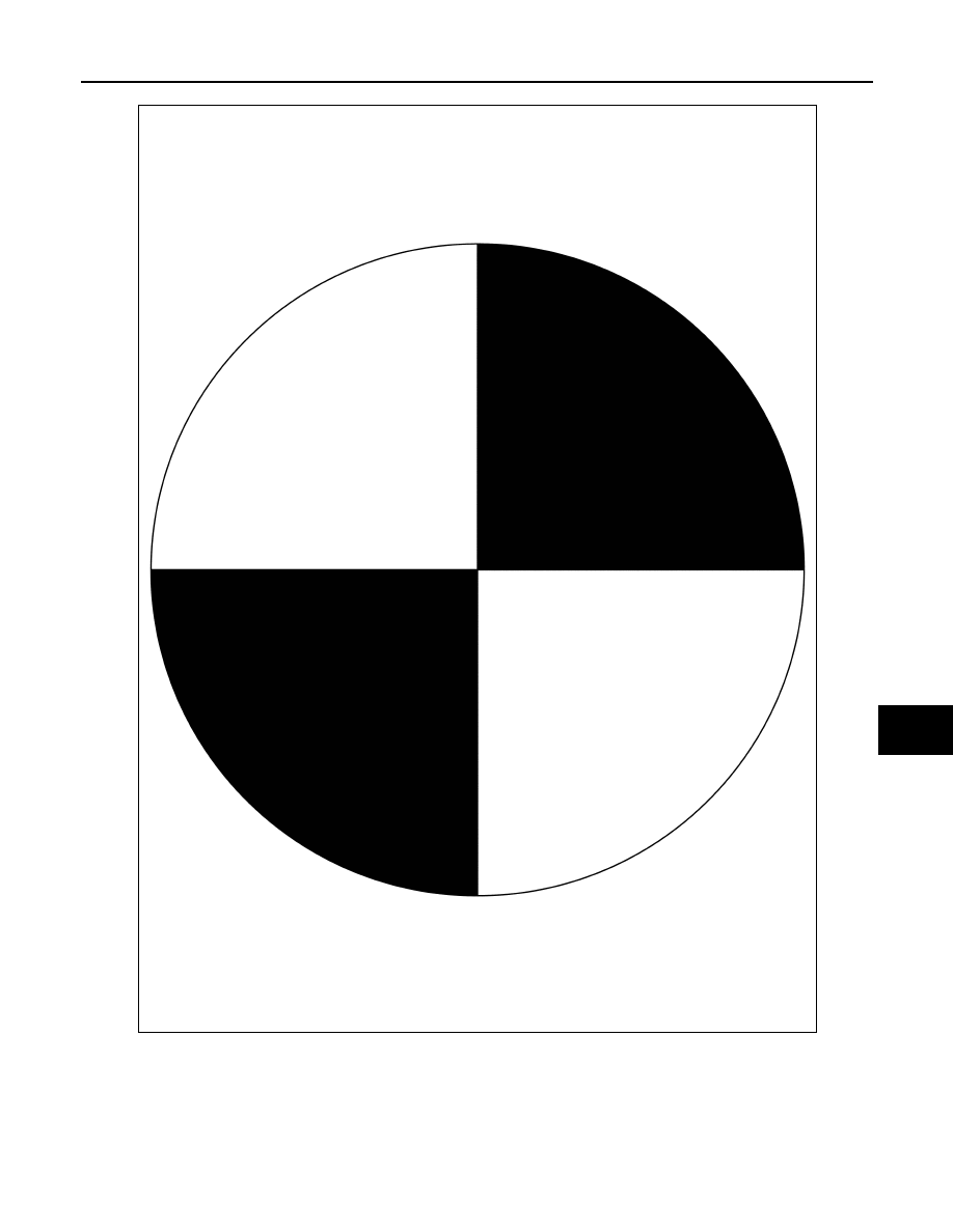
Target
NOTE:
Enlarge this page to 122% size and print it out.
PKIB4693E
LANE DEPARTURE WARNING SYSTEM
DI-73
< SERVICE INFORMATION >
C
D
E
F
G
H
I
J
L
M
A
B
DI
N
O
P
Target Setting
CAUTION:
• Perform this operation in a horizontal position where there is a clear view for 5 m (16.4 ft) forward
and 3 m (9.84 ft) wide.
• Place the target at a well-lighted location. (Poor lighting may make it hard to adjust.)
• The target may not be detected when there is a light source within 1.5 m (4.92 ft) from either side and
within 1 m (3.28 ft) upward/downward from the target.
• Make sure location of the sun. (Sunlight should not shine directly on front of the vehicle.)
PGIA0105J
DI-74
< SERVICE INFORMATION >
LANE DEPARTURE WARNING SYSTEM
• The target may not be detected when there is the same pattern of black and white as the target when
the pattern is within 1 m (3.28 ft) from either side and upward/downward position from the target. (It
is desirable that the vehicle is positioned on the opposite side of a single-color wall.)
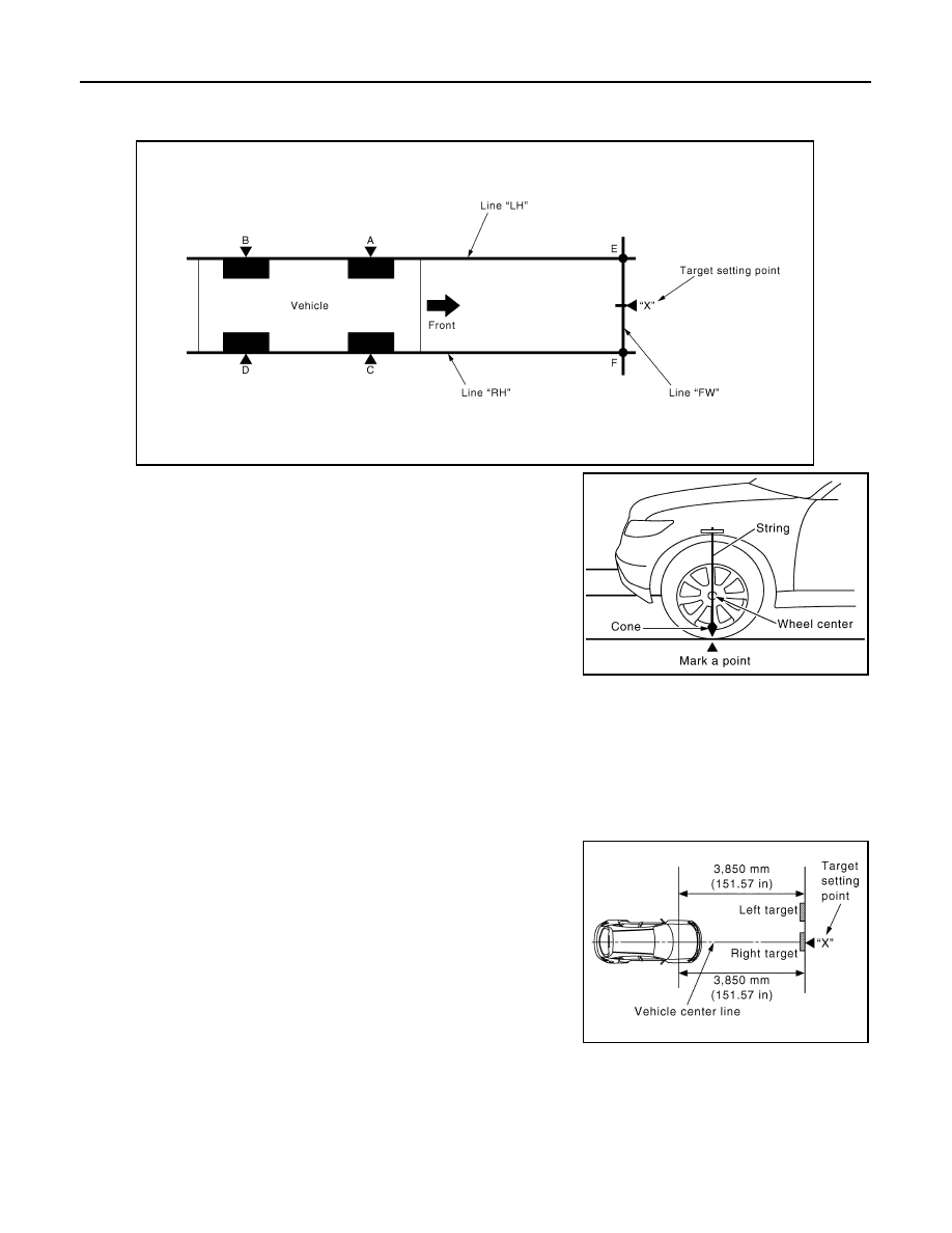
1.
Mark a point at the center of lateral surface of each wheels (“A”,
“B”, “C” and “D”).
NOTE:
Dangle a string with a cone from the fender so as to pass
through the center of wheel, and then mark a point at the center
of lateral surface of wheels.
2.
Draw a line passing through points “A” and “B” on the left side of
vehicle (line “LH”).
NOTE:
Approximately 4 m (13.12 ft) or more from the forward end of
vehicle.
3.
Mark points on the line “LH”, at the positions 3850 mm (151.57
in) from the point “A” (“E”).
4.
Draw a line passing through the points “C” and “D” on the right side of vehicle as with the step 2 (line
“RH”).
NOTE:
Approximately 4 m (13.12 ft) or more from the forward end of vehicle.
5.
Mark points on the line “RH”, at the positions 3850 mm (151.57 in) from the point “C” (“F”).
6.
Draw a line passing through the points “E” and “F” (line “FW”).
7.
Mark point at the center of the point “E” and “F”, on the line
“FW”.
CAUTION:
Make sure that “E” through “X” is equal to “F” through “X”.
8.
Position the center of the right target to the point of “X”.
VEHICLE HEIGHT CHECK
PKIB4694E
PKIB4695E
PKIB5331E
Нет комментариевНе стесняйтесь поделиться с нами вашим ценным мнением.
Текст