Infiniti FX35 / FX45. Manual — part 338
TROUBLE DIAGNOSIS
EC-113
< SERVICE INFORMATION >
[VQ35DE]
C
D
E
F
G
H
I
J
K
L
M
A
EC
N
P
O
34
OR
Intake air temperature sen-
sor
[Engine is running]
Approximately 0 - 4.8V
Output voltage varies with intake
air temperature.
40
41
42
LG
B
P
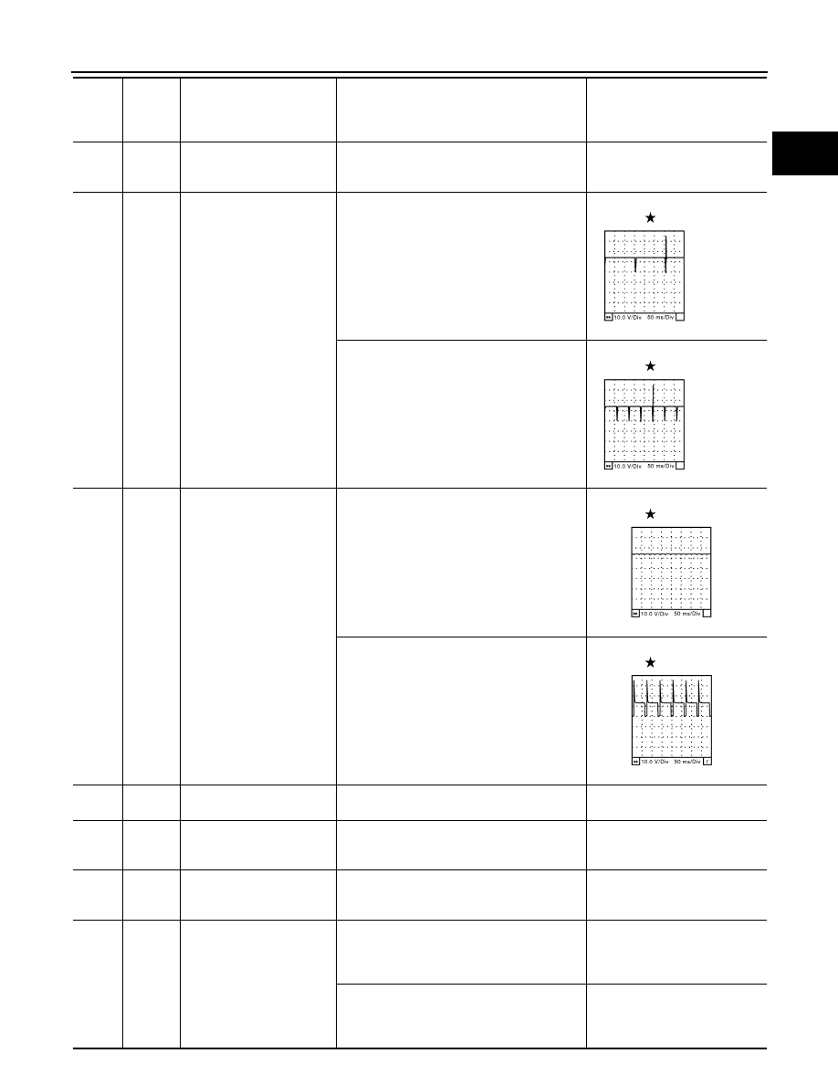
Fuel injector No. 6
Fuel injector No. 4
Fuel injector No. 2
[Engine is running]
• Warm-up condition
• Idle speed
NOTE:
The pulse cycle changes depending on rpm
at idle
BATTERY VOLTAGE
(11 - 14V)
[Engine is running]
• Warm-up condition
• Engine speed: 2,000 rpm
BATTERY VOLTAGE
(11 - 14V)
45
GY
EVAP canister purge volume
control solenoid valve
[Engine is running]
• Idle speed
• Accelerator pedal is not depressed even
slightly, after engine starting
BATTERY VOLTAGE
(11 - 14V)
[Engine is running]
• Engine speed is about 2,000 rpm (More than
100 seconds after starting engine)
BATTERY VOLTAGE
(11 - 14V)
47
L
Sensor power supply (Throt-
tle position sensor)
[Ignition switch: ON]
Approximately 5V
48
LG
Sensor power supply
(EVAP control system pres-
sure sensor)
[Ignition switch: ON]
Approximately 5V
49
PU
Sensor power supply
(Refrigerant pressure sen-
sor)
[Ignition switch: ON]
Approximately 5V
50
W
Throttle position sensor 1
[Ignition switch: ON]
• Engine stopped
• Selector lever: D
• Accelerator pedal: Fully released
More than 0.36V
[Ignition switch: ON]
• Engine stopped
• Selector lever: D
• Accelerator pedal: Fully depressed
Less than 4.75V
TER-
MI-
NAL
NO.
WIRE
COLOR
ITEM
CONDITION
DATA (DC Voltage)
SEC984C
SEC985C
SEC990C
SEC991C
EC-114
< SERVICE INFORMATION >
[VQ35DE]
TROUBLE DIAGNOSIS
51
L/W
Mass air flow sensor
[Engine is running]
• Warm-up condition
• Idle speed
1.0 - 1.2V
[Engine is running]
• Warm-up condition
• Engine speed: 2,500 rpm
1.6 - 2.0V
55
W/R
Heated oxygen sensor 2
(bank 2)
[Engine is running]
• Revving engine from idle to 3,000 rpm quick-
ly after the following conditions are met
- Engine: After warming up
- Keeping the engine speed between 3,500
and 4,000 rpm for 1 minute and at idle for 1
minute under no load
0 - Approximately 1.0V
57
G
A/F sensor 1 (Bank 2)
[Engine is running]
• Warm-up condition
• Idle speed
Approximately 2.6V
58
Y
Approximately 2.3V
76
P
Approximately 3.1V
77
BR
Approximately 2.3V
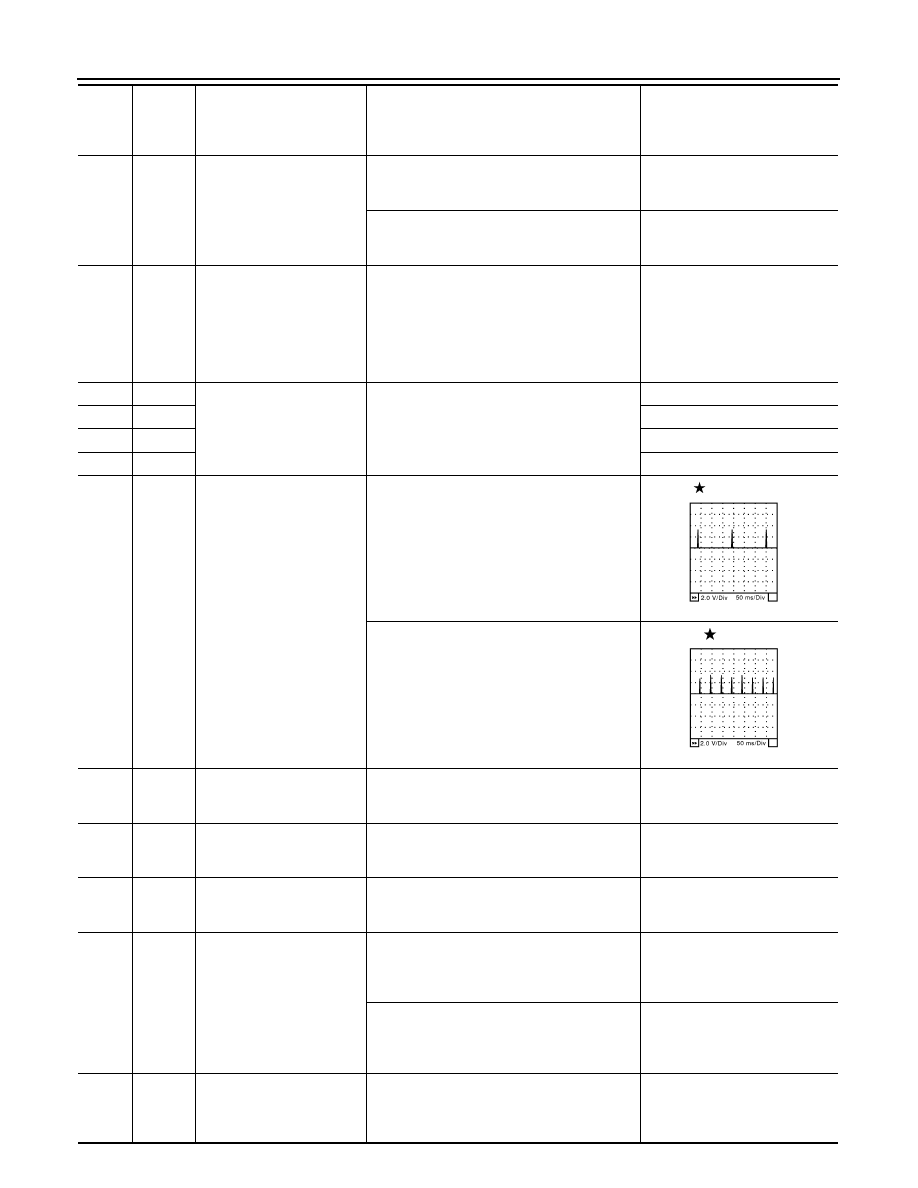
60
61
62
PU
L
Y
Ignition signal No. 5
Ignition signal No. 3
Ignition signal No. 1
[Engine is running]
• Warm-up condition
• Idle speed
NOTE:
The pulse cycle changes depending on rpm
at idle
0 - 0.2V
[Engine is running]
• Warm-up condition
• Engine speed: 2,500 rpm
0.1 - 0.4V
66
B
Sensor ground
(Throttle position sensor)
[Engine is running]
• Warm-up condition
• Idle speed
Approximately 0V
67
B/W
Sensor ground
[Engine is running]
• Warm-up condition
• Idle speed
Approximately 0V
68
BR
Sensor power supply
(Power steering pressure
sensor)
[Ignition switch: ON]
Approximately 5V
69
R
Throttle position sensor 2
[Ignition switch: ON]
• Engine stopped
• Selector lever: D
• Accelerator pedal: Fully released
Less than 4.75V
[Ignition switch: ON]
• Engine stopped
• Selector lever: D
• Accelerator pedal: Fully depressed
More than 0.36V
70
L/R
Refrigerant pressure sensor
[Engine is running]
• Warm-up condition
• Both A/C switch and blower fan switch: ON
(Compressor operates)
1.0 - 4.0V
TER-
MI-
NAL
NO.
WIRE
COLOR
ITEM
CONDITION
DATA (DC Voltage)
SEC986C
SEC987C
TROUBLE DIAGNOSIS
EC-115
< SERVICE INFORMATION >
[VQ35DE]
C
D
E
F
G
H
I
J
K
L
M
A
EC
N
P
O
73
Y
Engine coolant temperature
sensor
[Engine is running]
Approximately 0 - 4.8V
Output voltage varies with engine
coolant temperature.
74
LG/B
Heated oxygen sensor 2
(bank 1)
[Engine is running]
• Revving engine from idle to 3,000 rpm quick-
ly after the following conditions are met
- Engine: After warming up.
- Keeping the engine speed between 3,500
and 4,000 rpm for 1 minute and at idle for 1
minute under no load
0 - Approximately 1.0V
78
B/R
Sensor ground
(Heated oxygen sensor)
[Engine is running]
• Warm-up condition
• Idle speed
Approximately 0V
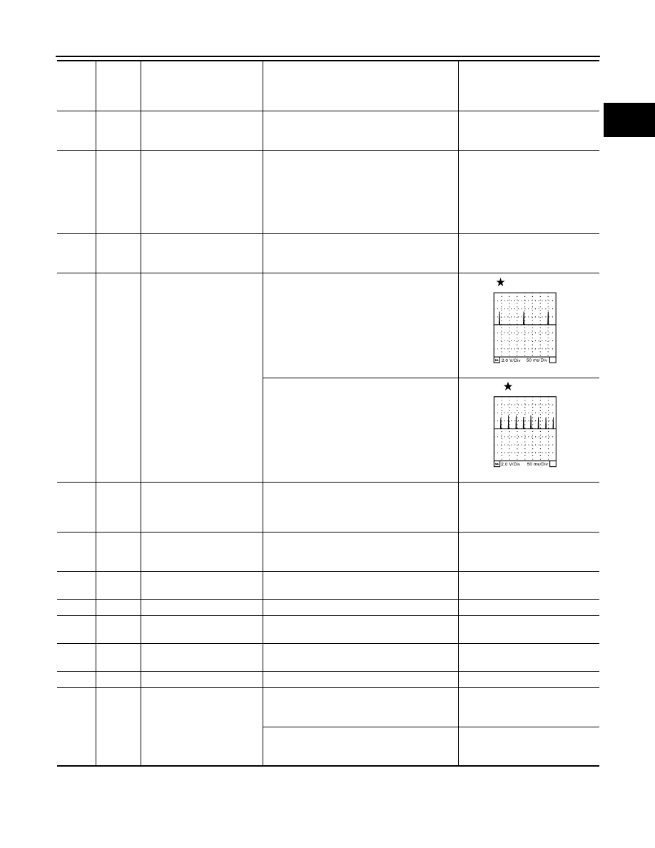
79
80
81
SB
GY
OR
Ignition signal No. 6
Ignition signal No. 4
Ignition signal No. 2
[Engine is running]
• Warm-up condition
• Idle speed
NOTE:
The pulse cycle changes depending on rpm
at idle
0 - 0.2V
[Engine is running]
• Warm-up condition
• Engine speed: 2,500 rpm
0.1 - 0.4V
82
B/W
Sensor ground
(APP sensor 1, ASCD steer-
ing switch, ICC steering
switch)
[Engine is running]
• Warm-up condition
• Idle speed
Approximately 0V
83
G/OR
Sensor ground
(APP sensor 2)
[Engine is running]
• Warm-up condition
• Idle speed
Approximately 0V
85
PU
Data link connector
[Ignition switch: ON]
• CONSULT-III or GST: Disconnected
Approximately 5V - Battery volt-
age (11 - 14V)
86
P
CAN communication line
—
—
90
L/B
Sensor power supply
(APP sensor 1)
[Ignition switch: ON]
Approximately 5V
91
G
Sensor power supply
(APP sensor 2)
[Ignition switch: ON]
Approximately 5V
94
L
CAN communication line
—
—
98
Y/R
Accelerator pedal position
sensor 2
[Ignition switch: ON]
• Engine stopped
• Accelerator pedal: Fully released
0.15 - 0.60V
[Ignition switch: ON]
• Engine stopped
• Accelerator pedal: Fully depressed
1.95 - 2.40V
TER-
MI-
NAL
NO.
WIRE
COLOR
ITEM
CONDITION
DATA (DC Voltage)
SEC986C
SEC987C

EC-116
< SERVICE INFORMATION >
[VQ35DE]
TROUBLE DIAGNOSIS
99
G/Y
ICC steering switch
(models with ICC system)
[Ignition switch: ON]
• ICC steering switch: OFF
Approximately 4.3V
[Ignition switch: ON]
• MAIN switch: Pressed
Approximately 0V
[Ignition switch: ON]
• CANCEL switch: Pressed
Approximately 1.3V
[Ignition switch: ON]
• RESUME/ACCELERATE switch: Pressed
Approximately 3.7V
[Ignition switch: ON]
• SET/COAST switch: Pressed
Approximately 3.0V
[Ignition switch: ON]
• DISTANCE switch: Pressed
Approximately 2.2V
99
G/Y
ASCD steering switch
(models with ASCD system)
[Ignition switch: ON]
• ASCD steering switch: OFF
Approximately 4.0V
[Ignition switch: ON]
• MAIN switch: Pressed
Approximately 0V
[Ignition switch: ON]
• CANCEL switch: Pressed
Approximately 1.0V
[Ignition switch: ON]
• RESUME/ACCELERATE switch: Pressed
Approximately 3.0V
[Ignition switch: ON]
• SET/COAST switch: Pressed
Approximately 2.0V
101
P/L
Stop lamp switch
[Ignition switch: OFF]
• Brake pedal: Fully released
Approximately 0V
[Ignition switch: OFF]
• Brake pedal: Slightly depressed
BATTERY VOLTAGE
(11 - 14V)
102
LG/B
PNP switch
[Ignition switch: ON]
• Selector lever: P or N
Approximately 0V
[Ignition switch: ON]
• Except above position
BATTERY VOLTAGE
(11 - 14V)
104
L/OR
Throttle control motor relay
[Ignition switch: OFF]
BATTERY VOLTAGE
(11 - 14V)
[Ignition switch: ON]
0 - 1.0V
106
OR
Accelerator pedal position
sensor 1
[Ignition switch: ON]
• Engine stopped
• Accelerator pedal: Fully released
0.5 - 1.0V
[Ignition switch: ON]
• Engine stopped
• Accelerator pedal: Fully depressed
3.9 - 4.7V
107
PU/W
Fuel tank temperature sen-
sor
[Engine is running]
Approximately 0 - 4.8V
Output voltage varies with fuel
tank temperature.
108
SB
ICC brake switch
(models with ICC system)
ASCD brake switch
(models with ASCD system)
[Ignition switch: ON]
• Brake pedal: Slightly depressed
Approximately 0V
[Ignition switch: ON]
• Brake pedal: Fully released
BATTERY VOLTAGE
(11 - 14V)
109
W/L
Ignition switch
[Ignition switch: OFF]
0V
[Ignition switch: ON]
BATTERY VOLTAGE
(11 - 14V)
TER-
MI-
NAL
NO.
WIRE
COLOR
ITEM
CONDITION
DATA (DC Voltage)
Нет комментариевНе стесняйтесь поделиться с нами вашим ценным мнением.
Текст