Infiniti FX35 / FX45. Manual — part 780

HEADLAMP - XENON TYPE -
LT-15
< SERVICE INFORMATION >
C
D
E
F
G
H
I
J
L
M
A
B
LT
N
O
P
2.
Understand operation description and function description. Refer to
.
3.
Perform Preliminary Check. Refer to
4.
Check symptom and repair or replace the cause of malfunction.
5.
Does headlamp operate normally? If YES, GO TO 6. If NO, GO TO 4.
6.
INSPECTION END
Preliminary Check
INFOID:0000000001328274
CHECK POWER SUPPLY AND GROUND CIRCUIT
1.
CHECK FUSES
Check for blown fuses.
LT-9, "Wiring Diagram - H/LAMP -"
OK or NG
OK
>> GO TO 2.
NG
>> If fuse is blown, be sure to eliminate cause of malfunction before installing new fuse. Refer to
2.
CHECK POWER SUPPLY CIRCUIT
1.
Turn ignition switch OFF.
2.
Disconnect BCM connector.
3.
Check voltage between BCM harness connector and ground.
OK or NG
OK
>> GO TO 3.
NG
>> Repair harness or connector.
3.
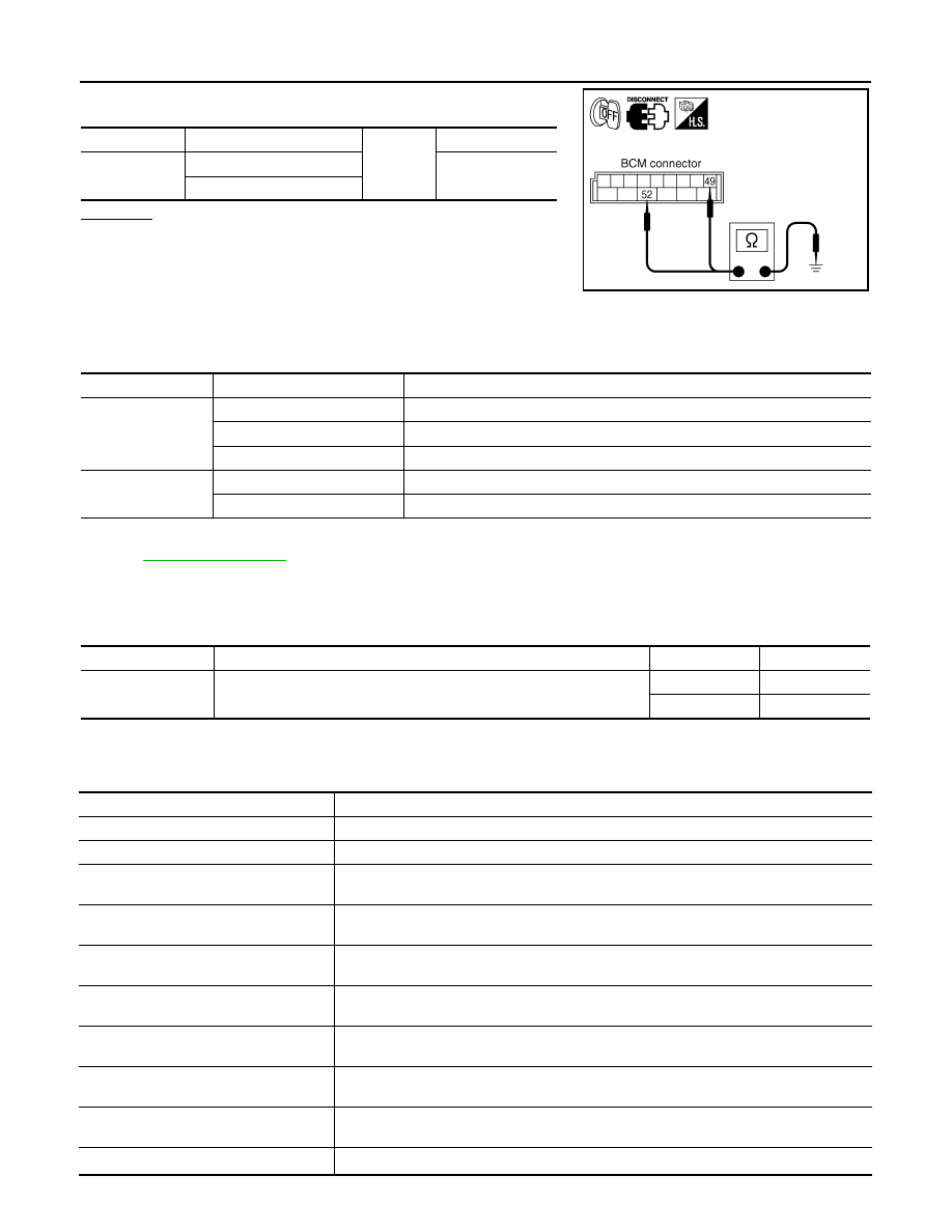
CHECK GROUND CIRCUIT
Unit
Power source
Fuse and fusible link No.
BCM
Battery
M
22
Ignition switch ON or START position
1
Ignition switch ACC or ON position
6
IPDM E/R
Battery
72
74
76
86
(+)
(-)
Ignition switch position
BCM con-
nector
Terminal
OFF
ACC
ON
M3
11
Ground
Approx. 0 V
Battery volt-
age
Battery volt-
age
38
Approx. 0 V
Approx. 0 V
Battery volt-
age
M4
42
Battery volt-
age
Battery volt-
age
Battery volt-
age
55
Battery volt-
age
Battery volt-
age
Battery volt-
age
PKIA5204E
LT-16
< SERVICE INFORMATION >
HEADLAMP - XENON TYPE -
Check continuity between BCM harness connector and ground.
OK or NG
OK
>> INSPECTION END
NG
>> Repair harness or connector.
CONSULT-III Functions (BCM)
INFOID:0000000001328275
CONSULT-III can display each diagnostic item using the diagnostic test mode shown following.
CONSULT-III BASIC OPERATION
.
WORK SUPPORT
Display Item List
DATA MONITOR
Display Item List
BCM connector
Terminal
Ground
Continuity
M4
49
Yes
52
SKIA5294E
BCM diagnosis part
Diagnosis mode
Description
HEADLAMP
WORK SUPPORT
Changes the setting for each function.
DATA MONITOR
Displays BCM input data in real time.
ACTIVE TEST
Operation of electrical loads can be checked by sending drive signal to them.
BCM
SELF-DIAG RESULTS
BCM performs self-diagnosis of CAN communication.
CAN DIAG SUPPORT MNTR
The result of transmit/receive diagnosis of CAN communication can be read.
Item
Description
CONSULT-III
Factory setting
BATTERY SAVER
SET
Exterior lamp battery saver control mode can be changed in this mode.
Selects exterior lamp battery saver control mode between two ON/OFF.
ON
×
OFF
—
Monitor item
Contents
IGN ON SW
“ON/OFF”
Displays “IGN position (ON)/OFF, ACC position (OFF)” judged from ignition switch signal.
ACC ON SW
“ON/OFF”
Displays “ACC (ON)/OFF, Ignition OFF (OFF)” status judged from ignition switch signal.
HI BEAM SW
“ON/OFF”
Displays status (high beam switch: ON/Others: OFF) of high beam switch judged from light-
ing switch signal.
HEAD LAMP SW 1
“ON/OFF”
Displays status (headlamp switch 1: ON/Others: OFF) of headlamp switch 1 judged from
lighting switch signal.
HEAD LAMP SW 2
“ON/OFF”
Displays status (headlamp switch 2: ON/Others: OFF) of headlamp switch 2 judged from
lighting switch signal.
LIGHT SW 1 ST
“ON/OFF”
Displays status (lighting switch 1ST or 2ND position: ON/Others: OFF) of lighting switch
judged from lighting switch signal.
AUTO LIGHT SW
NOTE 1
“ON/OFF”
Displays status of lighting switch as judged from lighting switch signal. (AUTO position: ON/
Other than AUTO position: OFF)
PASSING SW
“ON/OFF”
Displays status (flash-to-pass switch: ON/Others: OFF) of flash-to-pass switch judged from
lighting switch signal.
FR FOG SW
“ON/OFF”
Displays status (front fog lamp switch: ON/Others: OFF) of front fog lamp switch judged
from lighting switch signal.
RR FOG SW
NOTE 3
“OFF”
—

HEADLAMP - XENON TYPE -
LT-17
< SERVICE INFORMATION >
C
D
E
F
G
H
I
J
L
M
A
B
LT
N
O
P
NOTE:
1.
Vehicles without auto light system display this item, but cannot be monitored.
2.
Vehicles without daytime light system display this item, but cannot be monitored.
3.
This item is displayed, but cannot be monitored.
ACTIVE TEST
Display Item List
NOTE:
1.
Vehicles without daytime light lamp system display this item, but cannot be tested.
2.
This item is displayed, but cannot be tested.
CONSULT-III Functions (IPDM E/R)
INFOID:0000000001328276
CONSULT-III can display each diagnostic item using the diagnostic test modes shown following.
CONSULT-III BASIC OPERATION
.
DATA MONITOR
All Signals, Main Signals, Selection From Menu
DOOR SW - DR
“ON/OFF”
Displays status of driver door as judged from driver door switch signal. (Door is open: ON/
Door is closed: OFF)
DOOR SW - AS
“ON/OFF”
Displays status of passenger door as judged from passenger door switch signal. (Door is
open: ON/Door is closed: OFF)
DOOR SW - RR
“ON/OFF”
Displays status of rear door as judged from rear door switch (RH) signal. (Door is open: ON/
Door is closed: OFF)
DOOR SW - RL
“ON/OFF”
Displays status of rear door as judged from rear door switch (LH) signal. (Door is open: ON/
Door is closed: OFF)
BACK DOOR SW
“ON/OFF”
Displays status of back door as judged from back door switch signal. (Door is open: ON/
Door is closed: OFF)
TURN SIGNAL R
“ON/OFF”
Displays status (Turn right: ON/Others: OFF) as judged from lighting switch signal.
TURN SIGNAL L
“ON/OFF”
Displays status (Turn left: ON/Others: OFF) as judged from lighting switch signal.
ENGINE RUN
NOTE 2
“ON/OFF”
Displays status (Engine running: ON/Others: OFF) as judged from engine status signal.
PKB SW
NOTE 2
“ON/OFF”
Displays status (Parking brake switch: ON/Others: OFF) as judged from parking brake
switch signal.
CARGO LAMP SW
NOTE 3
“OFF”
—
OPTICAL SENSOR
NOTE 1
“0 - 5 V”
Displays “outside brightness (close to 5 V when light/close to 0 V when dark)” judged from
optical sensor signal.
Monitor item
Contents
Test item
Description
TAIL LAMP
Allows tail lamp relay to operate by switching ON-OFF.
HEAD LAMP
Allows headlamp relay to operate by switching ON-OFF.
FR FOG LAMP
Allows front fog lamp relay to operate by switching ON-OFF.
DTRL
NOTE 1
Allows daytime light lamp operate by switching ON-OFF
CORNERING LAMP
NOTE 2
—
Check Item, Diagnosis Mode
Description
SELF-DIAGNOSTIC RESULTS
Refer to
PG-18, "CONSULT-III Function (IPDM E/R)"
.
DATA MONITOR
The input/output data of IPDM E/R is displayed in real time.
CAN DIAG SUPPORT MNTR
The result of transmit/receive diagnosis of CAN communication can be read.
ACTIVE TEST
IPDM E/R sends a drive signal to electronic components to check their operation.

LT-18
< SERVICE INFORMATION >
HEADLAMP - XENON TYPE -
NOTE:
Perform monitoring of IPDM E/R data with ignition switch ON. When ignition switch is at ACC, display may not
be correct.
ACTIVE TEST
Headlamp Does Not Change To High Beam (Both Sides)
INFOID:0000000001381742
1.
CHECK COMBINATION SWITCH INPUT SIGNAL
CONSULT-III DATA MONITOR
1.
Select “HI BEAM SW” of BCM data monitor item.
2.
With operating the lighting switch, check the monitor status.
CHECK THE COMBINATION SWITCH
LT-104, "Combination Switch Inspection"
OK or NG
OK
>> GO TO 2.
NG
>> Check combination switch (lighting switch). Refer to
LT-104, "Combination Switch Inspection"
2.
HEADLAMP ACTIVE TEST
CONSULT-III ACTIVE TEST
1.
Select “LAMPS” of IPDM E/R active test item.
2.
With operating the test item, check the headlamp high beam operation.
IPDM E/R AUTO ACTIVE TEST
1.
Start auto active test. Refer to
2.
Check that the headlamp high beam operation.
OK or NG
OK
>> GO TO 3.
NG
>> GO TO 4.
3.
CHECK IPDM E/R
Item name
CONSULT-III
screen display
Display
or unit
Monitor item selection
Description
ALL
SIGNALS
MAIN
SIGNALS
SELECTION
FROM MENU
Position lights request
TAIL & CLR REQ
ON/OFF
×
×
×
Signal status input from BCM
Headlamp low beam request
HL LO REQ
ON/OFF
×
×
×
Signal status input from BCM
Headlamp high beam request
HL HI REQ
ON/OFF
×
×
×
Signal status input from BCM
Front fog lights request
FR FOG REQ
ON/OFF
×
×
×
Signal status input from BCM
Test item
CONSULT-III
screen display
Description
Headlamp relay (HI, LO) output
LAMPS
Allows headlamp relay (HI, LO) to operate by switching operation (OFF, HI ON,
LO ON) at your option (Headlamp high beam repeats ON-OFF every 1 second).
Front fog lamp relay output
Allows front fog lamp relay to operate by switching operation ON-OFF at your op-
tion.
Tail lamp relay output
TAIL LAMP
Allows tail lamp relay to operate by switching operation ON-OFF at your option.
When lighting switch is
HIGH BEAM
: HI BEAM SW ON
Headlamp high beam should operate.
(Headlamp high beam repeats ON-OFF every 1 second).
Headlamp high beam should operate.
Нет комментариевНе стесняйтесь поделиться с нами вашим ценным мнением.
Текст