Infiniti FX35 / FX45. Manual — part 526
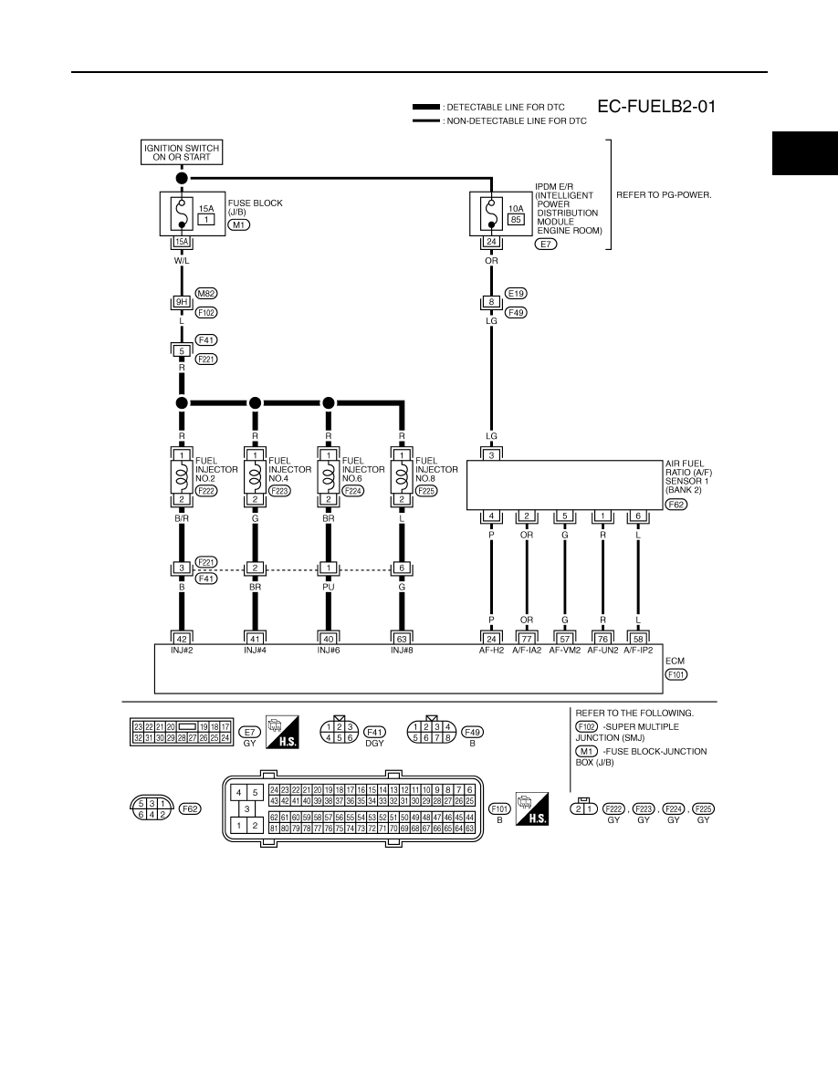
DTC P0171, P0174 FUEL INJECTION SYSTEM FUNCTION
EC-865
< SERVICE INFORMATION >
[VK45DE]
C
D
E
F
G
H
I
J
K
L
M
A
EC
N
P
O
BANK 2
Specification data are reference values and are measured between each terminal and ground.
Pulse signal is measured by CONSULT-III.
CAUTION:
Do not use ECM ground terminals when measuring input/output voltage. Doing so may result in dam-
age to the ECM's transistor. Use a ground other than ECM terminals, such as the ground.
TBWM1333E
EC-866
< SERVICE INFORMATION >
[VK45DE]
DTC P0171, P0174 FUEL INJECTION SYSTEM FUNCTION
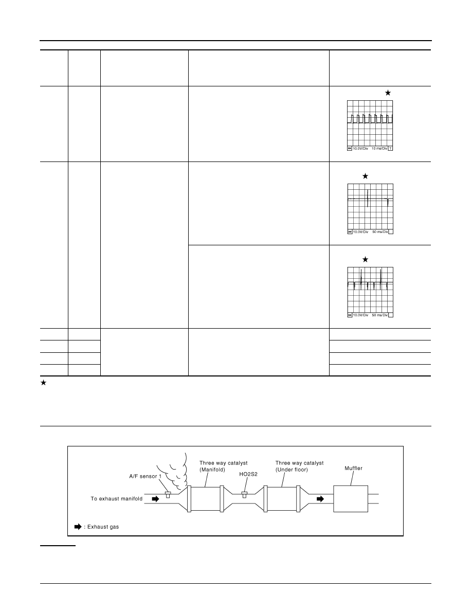
: Average voltage for pulse signal (Actual pulse signal can be confirmed by oscilloscope.)
Diagnosis Procedure
INFOID:0000000001326701
1.
CHECK EXHAUST GAS LEAK
1.
Start engine and run it at idle.
2.
Listen for an exhaust gas leak before three way catalyst (manifold).
OK or NG
OK
>> GO TO 2.
NG
>> Repair or replace.
2.
CHECK FOR INTAKE AIR LEAK
TER-
MI-
NAL
NO.
WIRE
COLOR
ITEM
CONDITION
DATA (DC Voltage)
24
P
A/F sensor 1 heater
(Bank 2)
[Engine is running]
• Warm-up condition
• Idle speed
Approximately 5V
40
41
42
63
PU
BR
B
G
Fuel injector No. 6
Fuel injector No. 4
Fuel injector No. 2
Fuel injector No. 8
[Engine is running]
• Warm-up condition
• Idle speed
NOTE:
The pulse cycle changes depending on rpm
at idle
BATTERY VOLTAGE
(11 - 14V)
[Engine is running]
• Warm-up condition
• Engine speed: 2,000 rpm
BATTERY VOLTAGE
(11 - 14V)
57
G
A/F sensor 1 (Bank 2)
[Engine is running]
• Warm-up condition
• Idle speed
Approximately 2.6V
58
L
Approximately 2.3V
76
R
Approximately 3.1V
77
OR
Approximately 2.3V
PBIB1584E
PBIB0042E
PBIB0043E
PBIB1216E
DTC P0171, P0174 FUEL INJECTION SYSTEM FUNCTION
EC-867
< SERVICE INFORMATION >
[VK45DE]
C
D
E
F
G
H
I
J
K
L
M
A
EC
N
P
O
1.
Listen for an intake air leak after the mass air flow sensor.
2.
Check PCV hose connection.
OK or NG
OK
>> GO TO 3.
NG
>> Repair or replace.
3.
CHECK AIR FUEL RATIO (A/F) SENSOR 1 INPUT SIGNAL CIRCUIT
1.
Turn ignition switch OFF.
2.
Disconnect air fuel ratio (A/F) sensor 1 harness connector.
3.
Disconnect ECM harness connector.
4.
Check harness continuity between the following terminals.
Refer to Wiring Diagram.
5.
Check harness continuity between the following terminals and ground.
Refer to Wiring Diagram.
6.
Also check harness for short to power.
OK or NG
OK
>> GO TO 4.
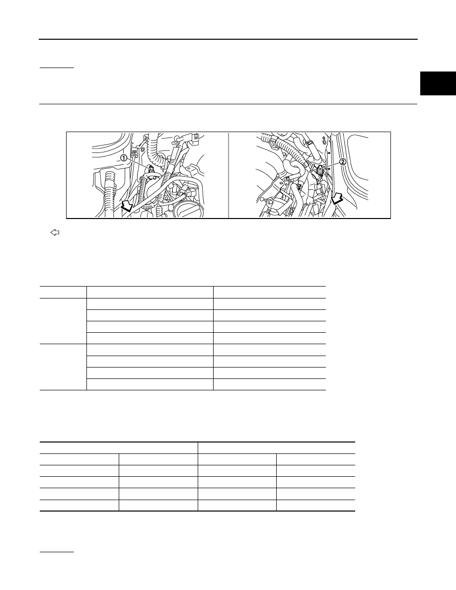
: Vehicle front
1.
A/F sensor 1 (Bank 2)
harness connector
2.
A/F sensor 1 (Bank 1)
harness connector
A/F sensor 1 terminal
ECM terminal
Bank 1
1
16
2
75
5
35
6
56
Bank 2
1
76
2
77
5
57
6
58
Continuity should exist.
Bank 1
Bank 2
A/F sensor 1 terminal
ECM terminal
A/F sensor 1 terminal
ECM terminal
1
16
1
76
2
75
2
77
5
35
5
57
6
56
6
58
Continuity should not exist.
PBIB3246E

EC-868
< SERVICE INFORMATION >
[VK45DE]
DTC P0171, P0174 FUEL INJECTION SYSTEM FUNCTION
NG
>> Repair open circuit or short to ground or short to power in harness or connectors.
4.
CHECK FUEL PRESSURE
1.
Release fuel pressure to zero. Refer to
2.
Install fuel pressure gauge and check fuel pressure. Refer to
OK or NG
OK
>> GO TO 6.
NG
>> GO TO 5.
5.
DETECT MALFUNCTIONING PART
Check the following.
• Fuel pump and circuit (Refer to
• Fuel pressure regulator (Refer to
• Fuel lines (Refer to
• Fuel filter for clogging
>> Repair or replace.
6.
CHECK MASS AIR FLOW SENSOR
With CONSULT-III
1.
Install all removed parts.
2.
Check “MASS AIR FLOW” in “DATA MONITOR” mode with CONSULT-III.
With GST
1.
Install all removed parts.
2.
Check mass air flow sensor signal in “Service $01” with GST.
OK or NG
OK (With CONSULT-III)>>GO TO 7.
OK (Without CONSULT-III)>>GO TO 8.
NG
>> Check connectors for rusted terminals or loose connections in the mass air flow sensor circuit or
grounds. Refer to
.
7.
CHECK FUNCTION OF FUEL INJECTOR-I
With CONSULT-III
1.
Start engine.
2.
Perform “POWER BALANCE” in “ACTIVE TEST” mode with CONSULT-III.
3.
Make sure that each circuit produces a momentary engine speed drop.
OK or NG
OK
>> GO TO 10.
NG
>> Perform trouble diagnosis for
.
8.
CHECK FUNCTION OF FUEL INJECTOR-I
Without CONSULT-III
1.
Turn ignition switch OFF.
2.
Disconnect harness connectors F21, F201 (Bank 1) and F41, F221 (Bank 2).
At idling: Approximately 350 kPa (3.57 kg/cm
2
, 51 psi)
2.0 - 6.0 g·m/sec:
at idling
7.0 - 20.0 g·m/sec:
at 2,500 rpm
2.0 - 6.0 g·m/sec:
at idling
7.0 - 20.0 g·m/sec:
at 2,500 rpm
Нет комментариевНе стесняйтесь поделиться с нами вашим ценным мнением.
Текст