Infiniti FX35 / FX45. Manual — part 214
INTELLIGENT KEY SYSTEM
BL-123
< SERVICE INFORMATION >
C
D
E
F
G
H
J
K
L
M
A
B
BL
N
O
P
OK or NG
OK
>> Replace Intelligent Key unit.
NG
>> Replace harness between outside key antenna and Intelligent Key unit.
Check Inside Key Antenna
INFOID:0000000001327862
1.
CHECK INSIDE KEY ANTENNA POWER SUPPLY CIRCUIT
Push ignition knob and use an oscilloscope to check voltage waveform between Intelligent Key unit connector
M34 terminals 13 (luggage room), 15 (dash board), 35 (dash board) and ground.
OK or NG
OK
>> GO TO 2.
NG
>> GO TO 3.
2.
CHECK INSIDE KEY ANTENNA OPERATION
1.
Disconnect inside key antenna connector.
2.
Check continuity between inside key antenna connector M70, M153 (dash board), B68 (luggage room)
terminals 1 and 2.
OK or NG
OK
>> GO TO 3.
NG
>> Replace malfunctioning inside key antenna.
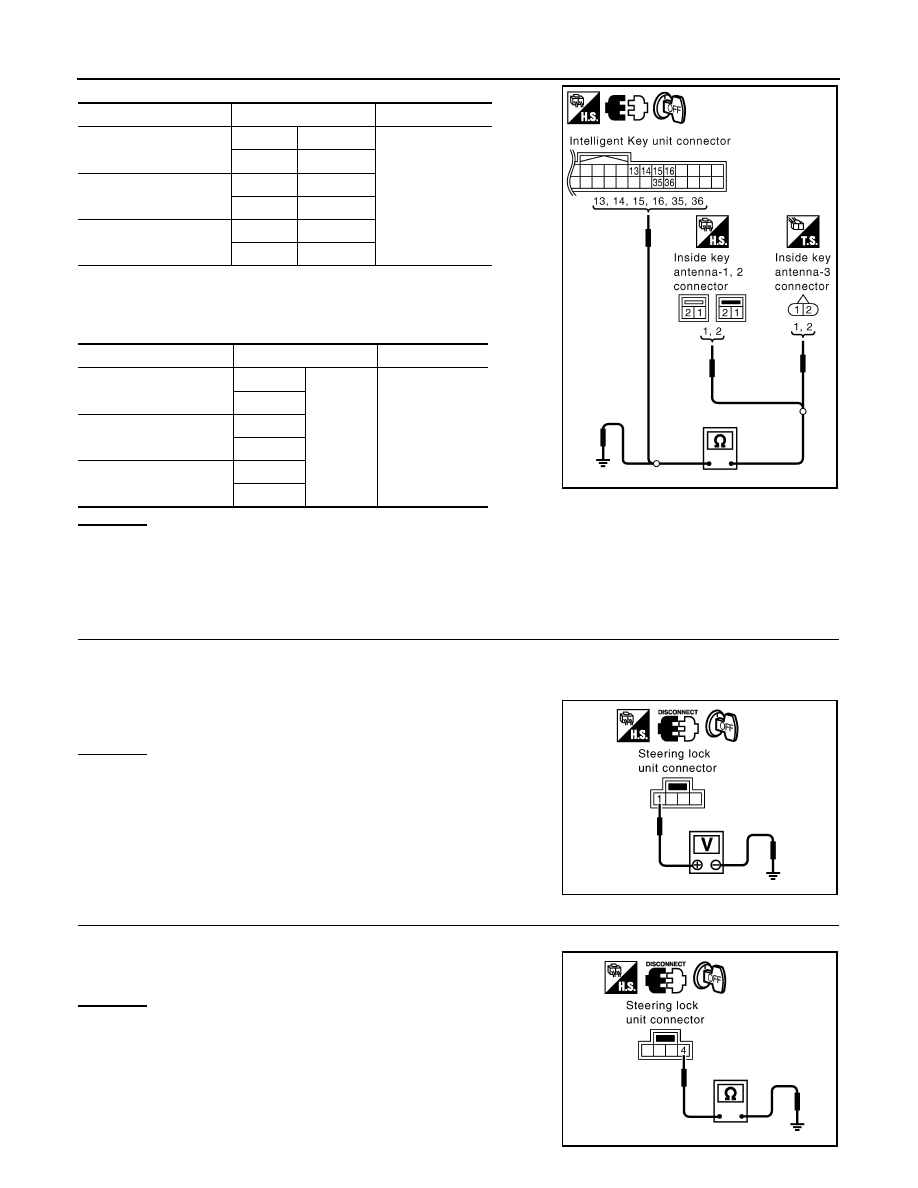
3.
CHECK INSIDE KEY ANTENNA
1.
Disconnect Intelligent Key unit connector.
2.
Check continuity between inside key antenna connector M70, M153 (dash board), B68 (luggage room)
terminals 1, 2 and Intelligent Key unit connector terminals 13, 14, 15, 16, 35 and 36.
Back door
1 (L/B)
Ground
No
2 (W/B)
Rear door
(LH, RH)
1 (G/Y)
2 (PU/W)
Driver side
14 (BR/W)
15 (R/Y)
Passenger side
14 (G/Y)
15 (L/Y)
Terminal (Wire color)
Condition
Signal
(Reference value)
(+)
(-)
Luggage room:
13 (P)
Ground
Push ignition
knob.
Dash board:
15 (G)
35 (LG)
PIIA6753E
SIIA1910J
1 - 2
: Continuity should exist.
PIIB8512E
BL-124
< SERVICE INFORMATION >
INTELLIGENT KEY SYSTEM
3.
Check continuity between inside key antenna connector M70,
M153 (dash board), B68 (luggage room) terminals 1 and 2 and
ground.
OK or NG
OK
>> Replace Intelligent Key unit.
NG
>> Repair or replace harness between inside key antenna and Intelligent Key unit.
Check Steering Lock Unit
INFOID:0000000001327863
1.
CHECK STEERING LOCK UNIT POWER SUPPLY
1.
Turn ignition knob LOCK position.
2.
Disconnect steering lock unit connector.
3.
Check voltage between steering lock unit connector M26 terminal 1 (L/R) and ground.
OK or NG
OK
>> GO TO 2.
NG
>> Repair or replace steering lock unit power supply circuit.
2.
CHECK STEERING LOCK UNIT GROUND CIRCUIT
Check continuity between steering lock unit connector M26 terminal 4 (Y/B) and ground.
OK or NG
OK
>> GO TO 3.
NG
>> GO TO 4.
Item
Terminal
Continuity
Inside key antenna-3
(Luggage room)
1 (OR/L)
13 (P)
Yes
2 (W/L)
14 (L)
Inside key antenna-1
(Dash board)
1 (G)
15 (G)
2 (R)
16 (R)
Inside key antenna-2
(Dash board)
1 (LG)
35 (LG)
2 (PU)
36 (PU)
Item
Terminal
Continuity
Inside key antenna-3
(Luggage room)
1 (OR/L)
Ground
No
2 (W/L)
Inside key antenna-1
(Dash board)
1 (G)
2 (R)
Inside key antenna-2
(Dash board)
1 (LG)
2 (PU)
PIIB8513E
1 (L/R) - Ground
: Battery voltage
PIIA6797E
4 (Y/B) - Ground
: Continuity should exist.
PIIA6798E
INTELLIGENT KEY SYSTEM
BL-125
< SERVICE INFORMATION >
C
D
E
F
G
H
J
K
L
M
A
B
BL
N
O
P
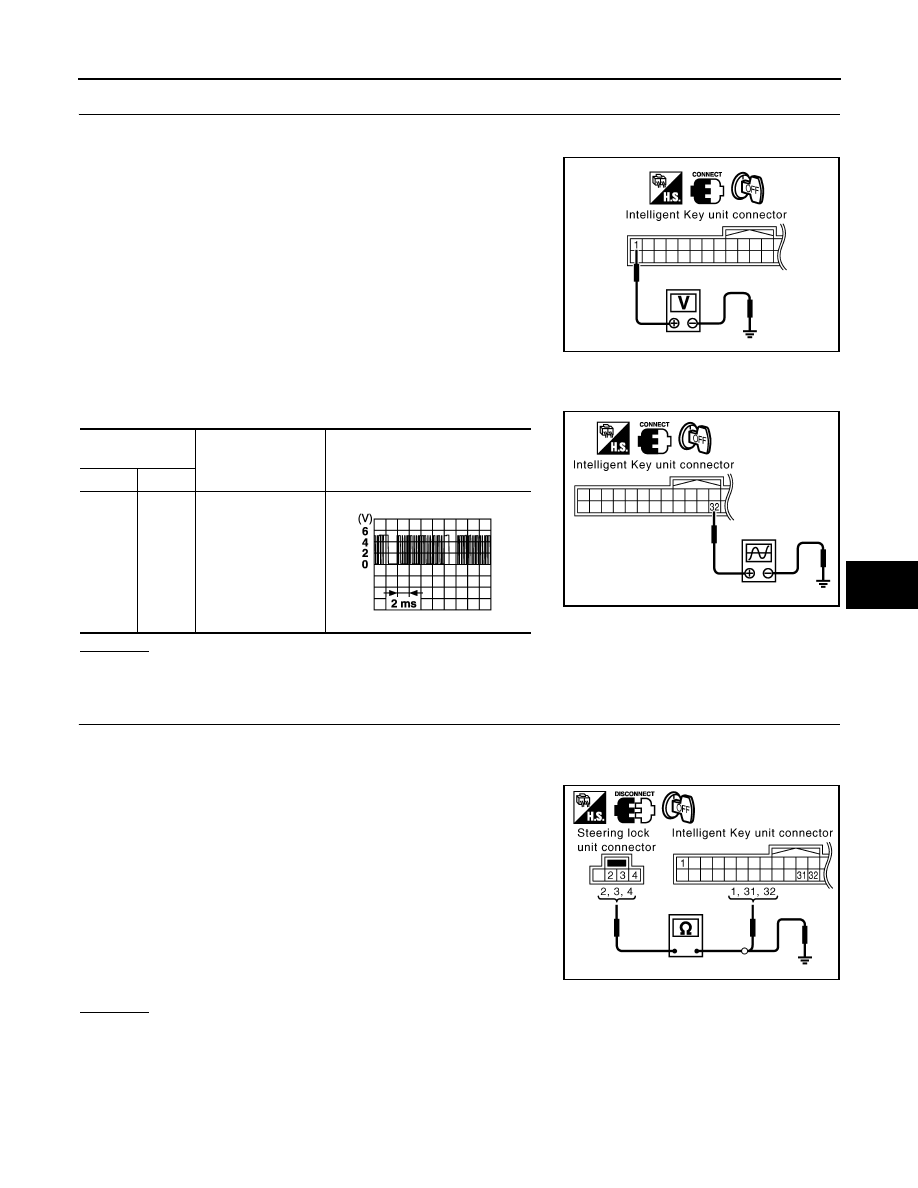
3.
CHECK STEERING LOCK COMMUNICATION CIRCUIT
1.
Connect steering lock unit connector.
2.
Check voltage between Intelligent Key unit connector M34 terminal 1 (R/W) and ground.
3.
Immediately after pushing ignition knob, use an oscilloscope to check voltage waveform between Intelli-
gent Key unit connector M34 terminal 32 (R/B) and ground.
OK or NG
OK
>> GO TO 4.
NG
>> Replace Intelligent Key unit.
4.
CHECK STEERING LOCK UNIT COMMUNICATION CIRCUIT
1.
Disconnect Intelligent Key unit and steering lock unit connectors.
2.
Check continuity between Intelligent Key unit connector M34 terminals 1, 31, 32 and steering lock unit
connector M26 terminals 2, 3, 4.
3.
Check continuity between steering lock unit connector M26 ter-
minals 2, 3, 4 and ground.
OK or NG
OK
>>
Replace steering lock unit.
• After replacing steering lock unit, perform registration procedure. Refer to “CONSULT-III Opera-
tion Manual NATS-IVIS/NVIS”.
NG
>> Repair or replace harness between steering lock unit and Intelligent Key unit.
1 (R/W) - Ground
: Approx. 5V
MIIB0385E
Terminal
(Wire color)
Condition
Signal
(Reference value)
(+)
(-)
32
(R/B)
Ground
Immediately after ig-
nition knob pushing.
MIIB0386E
SIIA1911J
1 (R/W) - 2 (R/W)
: Continuity should exist.
31 (Y/B) - 4 (Y/B)
: Continuity should exist.
32 (R/B) - 3 (R/B)
: Continuity should exist.
2 (R/W) - Ground
: Continuity should not exist.
3 (R/B) - Ground
: Continuity should not exist.
4 (Y/B) - Ground
: Continuity should not exist.
PIIA6799E
BL-126
< SERVICE INFORMATION >
INTELLIGENT KEY SYSTEM
Check Stop Lamp Switch
INFOID:0000000001327864
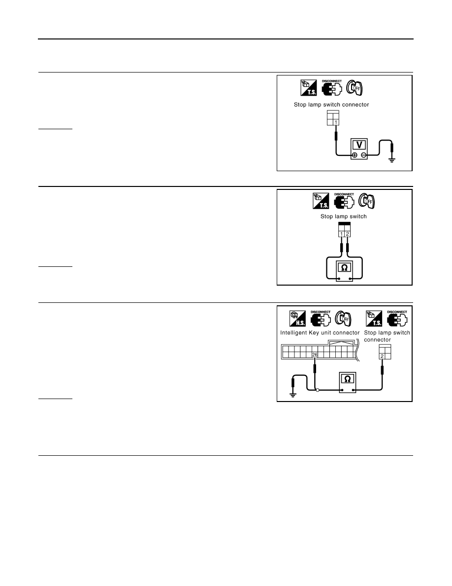
1.
CHECK STOP LAMP SWITCH POWER SUPPLY CIRCUIT
1.
Disconnect stop lamp switch connector.
2.
Check voltage between stop lamp switch connector E210 termi-
nal 1 (GY) and ground.
OK or NG
OK
>> GO TO 2.
NG
>> Repair or replace harness between stop lamp switch
and fuse.
2.
CHECK STOP LAMP SWITCH OPERATION
Check continuity between stop lamp switch connector E210 terminal
1 and 2.
OK or NG
OK
>> GO TO 3.
NG
>> Replace stop lamp switch.
3.
CHECK STOP LAMP SWITCH GROUND CIRCUIT
1.
Check continuity between stop lamp switch connector E210 ter-
minal 2 (P) and Intelligent Key unit connector M34 terminal 26
(P/L).
2.
Check continuity between stop lamp switch connector E210 ter-
minal 2 (P) and ground.
OK or NG
OK
>> Stop lamp switch is OK.
NG
>> Repair or replace harness.
Check Park Position Switch
INFOID:0000000001327865
1.
CHECK PARK POSITION SWITCH INPUT SIGNAL
1.
Turn ignition knob LOCK position.
2.
Check voltage between Intelligent Key unit connector and ground.
1 (GY) - Ground
: Battery voltage
PIIA6811E
1 - 2
Brake pedal depressed
: Continuity should exist.
Brake pedal not de-
pressed
: Continuity should not exist.
PIIA6800E
2 (P) - 26 (P/L)
: Continuity should exist.
2 (P) - Ground
: Continuity should not exist.
PIIA6801E
Нет комментариевНе стесняйтесь поделиться с нами вашим ценным мнением.
Текст