Infiniti FX35 / FX45. Manual — part 91

AT-292
< SERVICE INFORMATION >
REPAIR FOR COMPONENT PARTS
1.
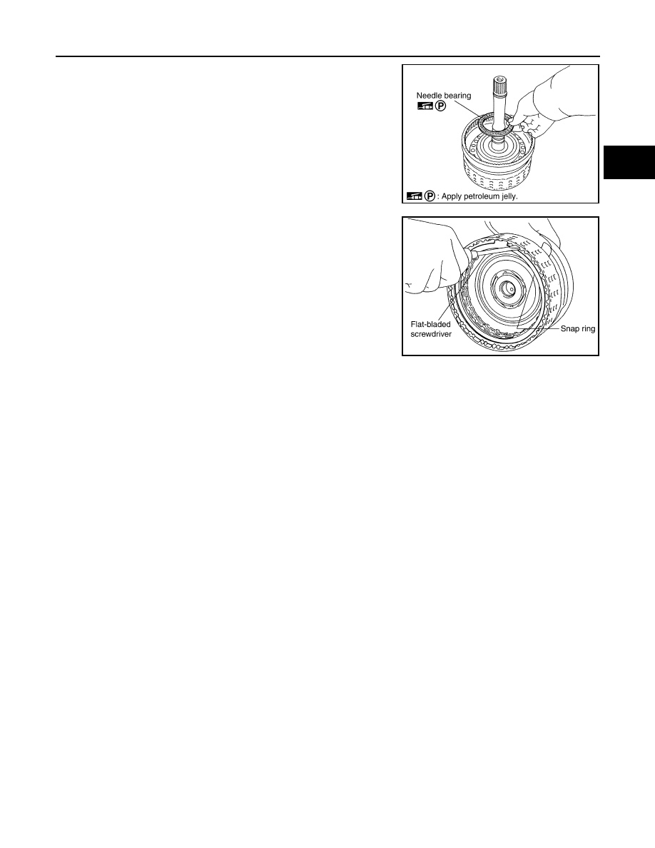
Compress snap ring using 2 flat-bladed screwdrivers.
2.
Remove front carrier assembly and input clutch assembly from
rear internal gear.
3.
Remove front carrier assembly from input clutch assembly.
a.
Remove bearing race from front carrier assembly.
b.
Remove needle bearing from front carrier assembly. (VK45DE
models)
c.
Remove snap ring from front carrier assembly.
CAUTION:
Do not expand snap ring excessively.
4.
Disassemble input clutch assembly.
a.
Remove O-ring and seal rings from input clutch assembly.
SCIA5339E
SCIA2847E
SCIA5233E
SCIA5476E
SCIA5235E
REPAIR FOR COMPONENT PARTS
AT-293
< SERVICE INFORMATION >
D
E
F
G
H
I
J
K
L
M
A
B
AT
N
O
P
b.
Remove needle bearing from input clutch assembly.
c.
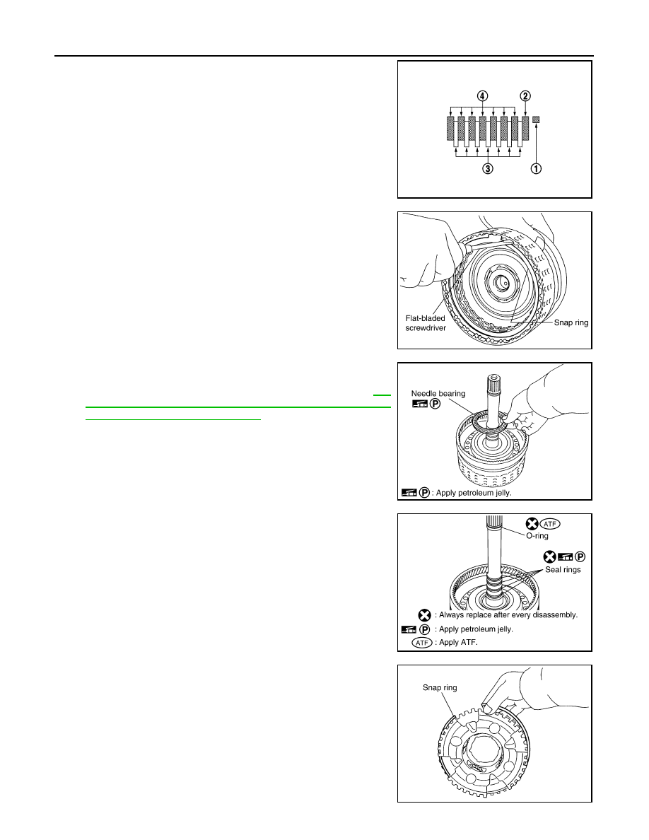
Using a flat-bladed screwdriver, remove snap ring from input
clutch drum.
d.
Remove drive plates, driven plates and retaining plate from input
clutch drum.
INSPECTION
Front Carrier Snap Ring
• Check for deformation, fatigue or damage.
CAUTION:
If necessary, replace the snap ring.
Input Clutch Snap Ring
• Check for deformation, fatigue or damage.
CAUTION:
If necessary, replace the input clutch assembly.
Input Clutch Drum
• Check for deformation, fatigue or damage or burns.
CAUTION:
If necessary, replace the input clutch assembly.
Input Clutch Drive Plates
• Check facing for burns, cracks or damage.
CAUTION:
If necessary, replace the input clutch assembly.
Input Clutch Retaining Plates and Driven Plates
• Check facing for burns, cracks or damage.
CAUTION:
If necessary, replace the input clutch assembly.
Front Carrier
• Check for deformation, fatigue or damage.
CAUTION:
If necessary, replace the front carrier assembly.
Rear Internal Gear
• Check for deformation, fatigue or damage.
CAUTION:
If necessary, replace the rear internal gear assembly.
ASSEMBLY
1.
Install input clutch.
SCIA2853E
SCIA2864E
AT-294
< SERVICE INFORMATION >
REPAIR FOR COMPONENT PARTS
a.
Install drive plates, driven plates and retaining plate in input
clutch drum.
• Snap ring (1)
• Retaining plate (2)
• Drive plate (3)
• Driven plate (4)
• Drive plate/Driven plate: 7/7
CAUTION:
Take care with order of plates.
b.
Using a flat-bladed screwdriver, install snap ring in input clutch
drum.
c.
Install needle bearing in input clutch assembly.
CAUTION:
• Take care with the direction of needle bearing. Refer
264, "Location of Adjusting Shims, Needle Bearings,
Thrust Washers and Snap Rings"
.
• Apply petroleum jelly to needle bearing.
d.
Install O-ring and seal rings in input clutch assembly.
CAUTION:
• Do not reuse O-ring and seal rings.
• Apply ATF to O-ring.
• Apply petroleum jelly to seal rings.
2.
Install front carrier assembly.
a.
Install snap ring to front carrier assembly.
CAUTION:
Do not expand snap ring excessively.
SCIA7133E
SCIA2864E
SCIA2853E
SCIA5235E
SCIA5476E

REPAIR FOR COMPONENT PARTS
AT-295
< SERVICE INFORMATION >
D
E
F
G
H
I
J
K
L
M
A
B
AT
N
O
P
b.
Install needle bearing in front carrier assembly. (VK45DE mod-
els)
CAUTION:
• Take care with the direction of needle bearing. Refer to
AT-264, "Location of Adjusting Shims, Needle Bearings,
Thrust Washers and Snap Rings"
.
• Apply petroleum jelly to needle bearing.
c.
Install bearing race in front carrier assembly.
CAUTION:
Apply petroleum jelly to bearing race.
d.
Install front carrier assembly to input clutch assembly.
3.
Compress snap ring using 2 flat-bladed screwdrivers.
4.
Install front carrier assembly and input clutch assembly to rear
internal gear.
Mid Sun Gear, Rear Sun Gear, High and Low Reverse Clutch Hub
INFOID:0000000001327407
COMPONENTS
VQ35DE models
SCIA5233E
SCIA2847E
SCIA5339E
SCIA2851E
Нет комментариевНе стесняйтесь поделиться с нами вашим ценным мнением.
Текст