Infiniti FX35 / FX45. Manual — part 503

DTC P0102, P0103 MAF SENSOR
EC-773
< SERVICE INFORMATION >
[VK45DE]
C
D
E
F
G
H
I
J
K
L
M
A
EC
N
P
O
8.
CHECK MASS AIR FLOW SENSOR
EC-773, "Component Inspection"
OK or NG
OK
>> GO TO 9.
NG
>> Replace mass air flow sensor.
9.
CHECK INTERMITTENT INCIDENT
>> INSPECTION END
Component Inspection
INFOID:0000000001326601
MASS AIR FLOW SENSOR
With CONSULT-III
1.
Reconnect all harness connectors disconnected.
2.
Start engine and warm it up to normal operating temperature.
3.
Connect CONSULT-III and select “DATA MONITOR” mode.
4.
Select “MAS A/F SE-B1” and check indication under the following conditions.
*: Check for linear voltage rise in response to engine being increased to about 4,000 rpm.
5.
If the voltage is out of specification, proceed the following.
a.
Check for the cause of uneven air flow through mass air flow sensor. Refer to following.
• Crushed air ducts
• Malfunctioning seal of air cleaner element
• Uneven dirt of air cleaner element
• Improper specification of intake air system parts
b.
If NG, repair or replace malfunctioning part and perform step 2 to 4 again.
If OK, go to next step.
6.
Turn ignition switch OFF.
7.
Disconnect mass air flow sensor harness connector and reconnect it again.
8.
Perform step 2 to 4 again.
9.
If NG, clean or replace mass air flow sensor.
Without CONSULT-III
1.
Reconnect all harness connectors disconnected.
2.
Start engine and warm it up to normal operating temperature.
Condition
MAS A/F SE-B1 (V)
Ignition switch ON (Engine stopped.)
Approx. 0.4
Idle (Engine is warmed-up to normal
operating temperature.)
1.0 - 1.3
2,500 rpm (Engine is warmed-up to
normal operating temperature.)
1.6 - 2.0
Idle to about 4,000 rpm
1.0 - 1.3 to Approx. 2.4*

EC-774
< SERVICE INFORMATION >
[VK45DE]
DTC P0102, P0103 MAF SENSOR
3.
Check voltage between ECM terminal 51 (Mass air flow sensor
signal) and ground.
*: Check for linear voltage rise in response to engine being increased to about 4,000 rpm.
4.
If the voltage is out of specification, proceed the following.
a.
Check for the cause of uneven air flow through mass air flow sensor. Refer to following.
• Crushed air ducts
• Malfunctioning seal of air cleaner element
• Uneven dirt of air cleaner element
• Improper specification of intake air system parts
b.
If NG, repair or replace malfunctioning part and perform step 2 and 3 again.
If OK, go to next step.
5.
Turn ignition switch OFF.
6.
Disconnect mass air flow sensor harness connector and reconnect it again.
7.
Perform step 2 and 3 again.
8.
If NG, clean or replace mass air flow sensor.
Removal and Installation
INFOID:0000000001326602
MASS AIR FLOW SENSOR
.
Condition
Voltage V
Ignition switch ON (Engine stopped.)
Approx. 0.4
Idle (Engine is warmed-up to normal
operating temperature.)
1.0 - 1.3
2,500 rpm (Engine is warmed-up to
normal operating temperature.)
1.6 - 2.0
Idle to about 4,000 rpm
1.0 - 1.3 to Approx. 2.4*
PBIB1106E
DTC P0112, P0113 IAT SENSOR
EC-775
< SERVICE INFORMATION >
[VK45DE]
C
D
E
F
G
H
I
J
K
L
M
A
EC
N
P
O
DTC P0112, P0113 IAT SENSOR
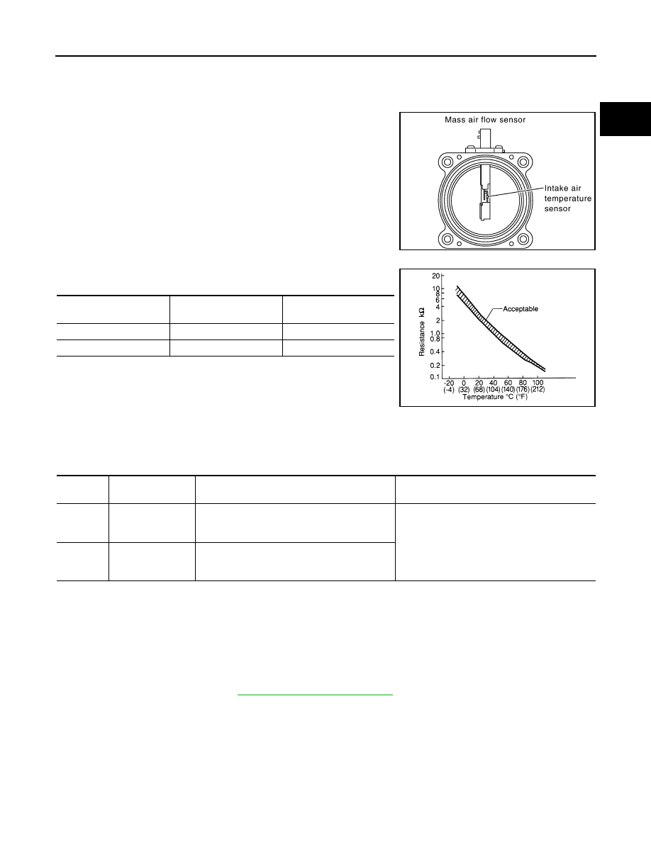
Component Description
INFOID:0000000001326603
The intake air temperature sensor is built-into mass air flow sensor.
The sensor detects intake air temperature and transmits a signal to
the ECM.
The temperature sensing unit uses a thermistor which is sensitive to
the change in temperature. Electrical resistance of the thermistor
decreases in response to the temperature rise.
<Reference data>
*: These data are reference values and are measured between ECM terminal 34
(Intake air temperature sensor) and ground.
CAUTION:
Do not use ECM ground terminals when measuring input/output
voltage. Doing so may result in damage to the ECM's transistor.
Use a ground other than ECM terminals, such as the ground.
On Board Diagnosis Logic
INFOID:0000000001326604
DTC Confirmation Procedure
INFOID:0000000001326605
NOTE:
If DTC Confirmation Procedure has been previously conducted, always turn ignition switch OFF and wait at
least 10 seconds before conducting the next test.
1.
Turn ignition switch ON and wait at least 5 seconds.
2.
Check 1st trip DTC.
3.
If 1st trip DTC is detected, go to
PBIB1604E
Intake air temperature
°
C (
°
F)
Voltage*
V
Resistance
k
Ω
25 (77)
3.3
1.800 - 2.200
80 (176)
1.2
0.283 - 0.359
SEF012P
DTC No.
Trouble diagnosis
name
DTC detecting condition
Possible cause
P0112
0112
Intake air tempera-
ture sensor circuit
low input
An excessively low voltage from the sensor is
sent to ECM.
• Harness or connectors
(The sensor circuit is open or shorted.)
• Intake air temperature sensor
P0113
0113
Intake air tempera-
ture sensor circuit
high input
An excessively high voltage from the sensor is
sent to ECM.
EC-776
< SERVICE INFORMATION >
[VK45DE]
DTC P0112, P0113 IAT SENSOR
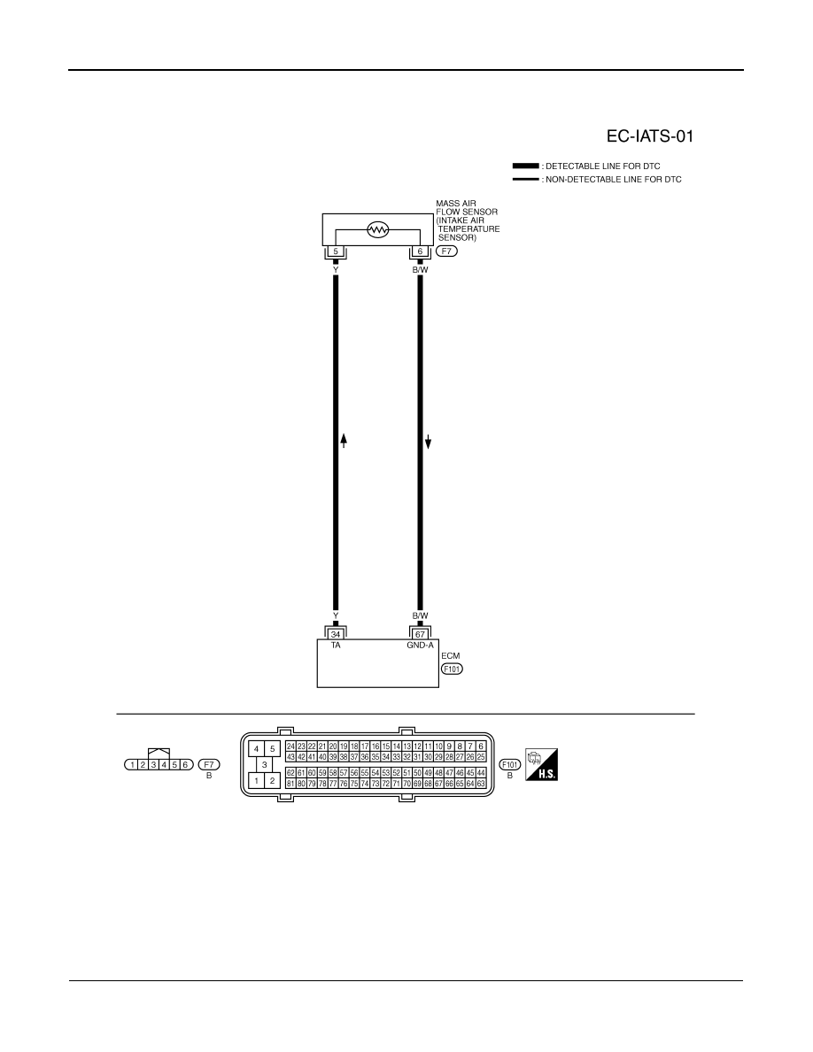
Wiring Diagram
INFOID:0000000001326606
Diagnosis Procedure
INFOID:0000000001326607
1.
CHECK GROUND CONNECTIONS
1.
Turn ignition switch OFF.
2.
Loosen and retighten three ground screws on the body.
TBWM0723E
Нет комментариевНе стесняйтесь поделиться с нами вашим ценным мнением.
Текст