Infiniti FX35 / FX45. Manual — part 523
DTC P0139, P0159 HO2S2
EC-853
< SERVICE INFORMATION >
[VK45DE]
C
D
E
F
G
H
I
J
K
L
M
A
EC
N
P
O
WITH CONSULT-III
TESTING CONDITION:
For better results, perform “DTC WORK SUPPORT” at a temperature of 0 to 30
°
C (32 to 86
°
F).
1.
Turn ignition switch ON and select “COOLAN TEMP/S” in “DATA MONITOR” mode with CONSULT-III.
2.
Start engine and warm it up to the normal operating temperature.
3.
Turn ignition switch OFF and wait at least 10 seconds.
4.
Start engine and keep the engine speed between 3,500 and 4,000 rpm for at least 1 minute under no load.
5.
Let engine idle for 1 minute.
6.
Check that “COOLAN TEMP/S” indicates more than 70
°
C (158
°
F).
If not, warm up engine and go to next step when “COOLAN TEMP/S” indication reaches to 70
°
C (158
°
F).
7.
Select “HO2S2 (B1) P0139” or “HO2S2 (B2) P0159” of “HO2S2” in “DTC WORK SUPPORT” mode with
CONSULT-III.
8.
Start engine and following the instruction of CONSULT-III.
NOTE:
It will take at most 10 minutes until “COMPLETED” is displayed.
9.
Make sure that “OK” is displayed after touching “SELF-DIAG RESULTS”.
If “NG” is displayed, refer to
.
If “CAN NOT BE DIAGNOSED” is displayed, perform the following.
a.
Turn ignition switch OFF and leave the vehicle in a cool place (soak the vehicle).
b.
Return to step 1.
Overall Function Check
INFOID:0000000001326693
Use this procedure to check the overall function of the heated oxygen sensor 2 circuit. During this check, a 1st
trip DTC might not be confirmed.
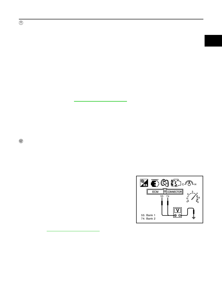
WITH GST
1.
Start engine and warm it up to the normal operating temperature.
2.
Turn ignition switch OFF and wait at least 10 seconds.
3.
Start engine and keep the engine speed between 3,500 and 4,000 rpm for at least 1 minute under no load.
4.
Let engine idle for 1 minute.
5.
Set voltmeter probes between ECM terminal 55 [HO2S2 (B1) signal] or 74 [HO2S2 (B2) signal] and
ground.
6.
Check the voltage when revving up to 4,000 rpm under no load
at least 10 times.
(Depress and release accelerator pedal as soon as possible.)
A change of voltage should be more than 0.12V for 1 sec-
ond during this procedure.
If the voltage can be confirmed in step 6, step 7 is not nec-
essary.
7.
Keep vehicle at idling for 10 minutes, then check the voltage. Or
check the voltage when coasting from 80 km/h (50 MPH) in D
position.
A change of voltage should be more than 0.12V for 1 sec-
ond during this procedure.
8.
If NG, go to
PBIB2024E
EC-854
< SERVICE INFORMATION >
[VK45DE]
DTC P0139, P0159 HO2S2
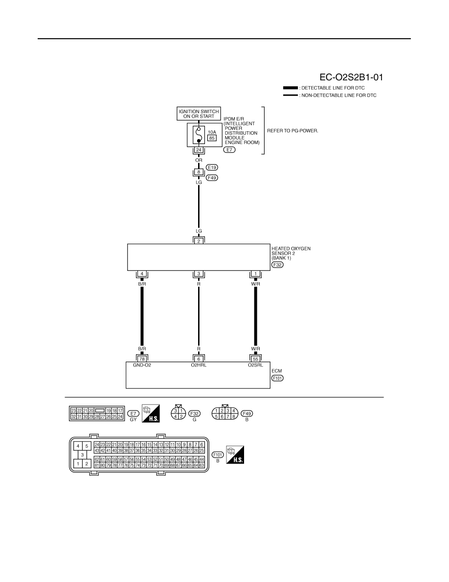
Wiring Diagram
INFOID:0000000001326694
BANK 1
Specification data are reference values and are measured between each terminal and ground.
CAUTION:
Do not use ECM ground terminals when measuring input/output voltage. Doing so may result in dam-
age to the ECM's transistor. Use a ground other than ECM terminals, such as the ground.
TBWM1330E

DTC P0139, P0159 HO2S2
EC-855
< SERVICE INFORMATION >
[VK45DE]
C
D
E
F
G
H
I
J
K
L
M
A
EC
N
P
O
TER-
MI-
NAL
NO.
WIRE
COLOR
ITEM
CONDITION
DATA (DC Voltage)
6
R
Heated oxygen sensor 2
heater (Bank 1)
[Engine is running]
• Engine speed: Below 3,600 rpm after the fol-
lowing conditions are met
- Engine: After warming up
- Keeping the engine speed between 3,500
and 4,000 rpm for 1 minute and at idle for 1
minute under no load
0 - 1.0V
[Ignition switch: ON]
• Engine stopped
[Engine is running]
• Engine speed: Above 3,600 rpm
BATTERY VOLTAGE
(11 - 14V)
55
W/R
Heated oxygen sensor 2
(Bank 1)
[Engine is running]
• Revving engine from idle to 3,000 rpm quick-
ly after the following conditions are met
- Engine: After warming up
- After keeping the engine speed between
3,500 and 4,000 rpm for 1 minute and at idle
for 1 minute under no load
0 - Approximately 1.0V
78
B/R
Sensor ground
(Heated oxygen sensor 2)
[Engine is running]
• Warm-up condition
• Idle speed
Approximately 0V
EC-856
< SERVICE INFORMATION >
[VK45DE]
DTC P0139, P0159 HO2S2
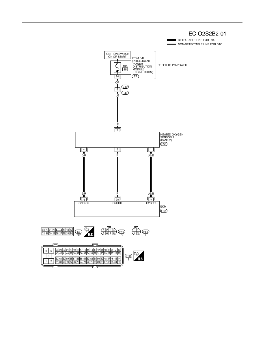
BANK 2
Specification data are reference values and are measured between each terminal and ground.
CAUTION:
Do not use ECM ground terminals when measuring input/output voltage. Doing so may result in dam-
age to the ECM's transistor. Use a ground other than ECM terminals, such as the ground.
TBWM1331E
Нет комментариевНе стесняйтесь поделиться с нами вашим ценным мнением.
Текст