Infiniti FX35 / FX45. Manual — part 490

POWER SUPPLY AND GROUND CIRCUIT
EC-721
< SERVICE INFORMATION >
[VK45DE]
C
D
E
F
G
H
I
J
K
L
M
A
EC
N
P
O
3.
Check voltage between ECM terminals 119, 120 and ground
with CONSULT-III or tester.
OK or NG
OK
>> GO TO 15.
NG (Battery voltage does not exist.)>>GO TO 9.
NG (Battery voltage exists for more than a few seconds.)>>GO TO
12.
9.
CHECK ECM POWER SUPPLY CIRCUIT-IV
Check voltage between ECM terminal 111 and ground with CON-
SULT-III or tester.
OK or NG
OK
>> GO TO 10.
NG
>> GO TO 12.
10.
CHECK ECM POWER SUPPLY CIRCUIT-V
1.
Disconnect ECM harness connector.
2.
Disconnect IPDM E/R harness connector E7.
3.
Check harness continuity between ECM terminals 119, 120 and IPDM E/R terminal 18.
Refer to Wiring Diagram.
4.
Also check harness for short to ground and short to power.
OK or NG
OK
>> GO TO 18.
NG
>> GO TO 11.
11.
DETECT MALFUNCTIONING PART
Check the following.
• Harness connectors E211, M41
• Harness for open or short between ECM and IPDM E/R
>> Repair open circuit or short to ground or short to power in harness or connectors.
12.
CHECK ECM POWER SUPPLY CIRCUIT-VI
1.
Disconnect ECM harness connector.
2.
Disconnect IPDM E/R harness connector E9.
3.
Check harness continuity between ECM terminal 111 and IPDM E/R terminal 46.
Refer to Wiring Diagram.
4.
Also check harness for short to ground and short to power.
OK or NG
OK
>> GO TO 14.
NG
>> GO TO 13.
13.
DETECT MALFUNCTIONING PART
Voltage:
After turning ignition switch OFF, battery
voltage will exist for a few seconds, then drop
approximately 0V.
PBIB1630E
Voltage: Battery voltage
PBIB1191E
Continuity should exist.
Continuity should exist.
EC-722
< SERVICE INFORMATION >
[VK45DE]
POWER SUPPLY AND GROUND CIRCUIT
Check the following.
• Harness connectors E211, M41
• Harness for open or short between ECM and IPDM E/R
>> Repair open circuit or short to ground or short to power in harness or connectors.
14.
CHECK 20A FUSE
1.
Disconnect 20A fuse from IPDM E/R.
2.
Check 20A fuse.
OK or NG
OK
>> GO TO 18.
NG
>> Replace 20A fuse.
15.
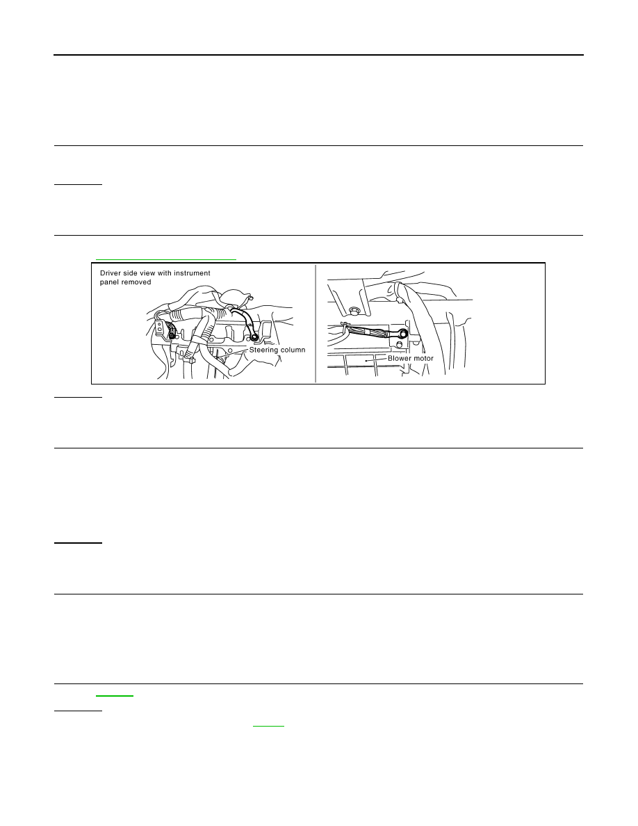
CHECK GROUND CONNECTIONS
Loosen and retighten three ground screws on the body.
Refer to
OK or NG
OK
>> GO TO 16.
NG
>> Repair or replace ground connections.
16.
CHECK ECM GROUND CIRCUIT FOR OPEN AND SHORT-II
1.
Disconnect ECM harness connector.
2.
Check harness continuity between ECM terminals 1, 115, 116 and ground.
Refer to Wiring Diagram.
3.
Also check harness for short to power.
OK or NG
OK
>> GO TO 18.
NG
>> GO TO 17.
17.
DETECT MALFUNCTIONING PART
Check the following.
• Harness connectors F102, M82
• Harness for open or short between ECM and ground
>> Repair open circuit or short to power in harness or connectors.
18.
CHECK INTERMITTENT INCIDENT
OK or NG
OK
>> Replace IPDM E/R. Refer to
.
NG
>> Repair open circuit or short to power in harness or connectors.
PBIB2195E
Continuity should exist.
POWER SUPPLY AND GROUND CIRCUIT
EC-723
< SERVICE INFORMATION >
[VK45DE]
C
D
E
F
G
H
I
J
K
L
M
A
EC
N
P
O
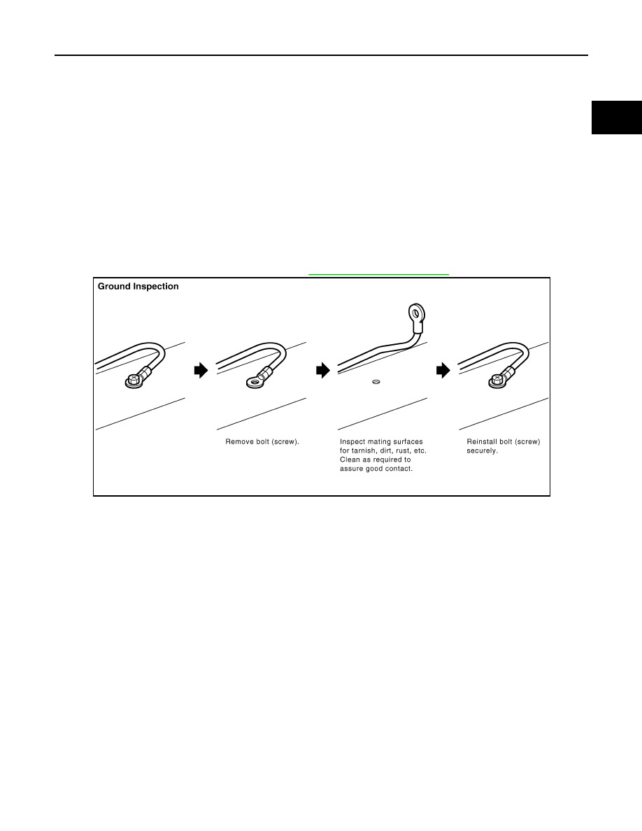
Ground Inspection
INFOID:0000000001326544
Ground connections are very important to the proper operation of electrical and electronic circuits. Ground
connections are often exposed to moisture, dirt and other corrosive elements. The corrosion (rust) can
become an unwanted resistance. This unwanted resistance can change the way a circuit works.
Electronically controlled circuits are very sensitive to proper grounding. A loose or corroded ground can drasti-
cally affect an electronically controlled circuit. A poor or corroded ground can easily affect the circuit. Even
when the ground connection looks clean, there can be a thin film of rust on the surface.
When inspecting a ground connection follow these rules:
• Remove the ground bolt or screw.
• Inspect all mating surfaces for tarnish, dirt, rust, etc.
• Clean as required to assure good contact.
• Reinstall bolt or screw securely.
• Inspect for “add-on” accessories which may be interfering with the ground circuit.
• If several wires are crimped into one ground eyelet terminal, check for proper crimps. Make sure all of the
wires are clean, securely fastened and providing a good ground path. If multiple wires are cased in one eye-
let make sure no ground wires have excess wire insulation.
For detailed ground distribution information, refer to
PBIB1870E

EC-724
< SERVICE INFORMATION >
[VK45DE]
DTC U1000, U1001 CAN COMMUNICATION LINE
DTC U1000, U1001 CAN COMMUNICATION LINE
Description
INFOID:0000000001326545
CAN (Controller Area Network) is a serial communication line for real time application. It is an on-vehicle mul-
tiplex communication line with high data communication speed and excellent error detection ability. Many elec-
tronic control units are equipped onto a vehicle, and each control unit shares information and links with other
control units during operation (not independent). In CAN communication, control units are connected with 2
communication lines (CAN H line, CAN L line) allowing a high rate of information transmission with less wiring.
Each control unit transmits/receives data but selectively reads required data only.
On Board Diagnosis Logic
INFOID:0000000001326546
*1: This self-diagnosis has the one trip detection logic.
*2: The MIL will not light up for this diagnosis.
*3: This self-diagnosis has one or two trip detection logic.
DTC Confirmation Procedure
INFOID:0000000001326547
1.
Turn ignition switch ON and wait at least 3 seconds.
2.
Check 1st trip DTC.
3.
If 1st trip DTC is detected, go to
DTC No.
Trouble diagnosis
name
DTC detecting condition
Possible cause
U1000*
1
1000*
1
CAN communication
line
When ECM is not transmitting or receiving CAN
communication signal of OBD (emission-related
diagnosis) for 2 seconds or more.
• Harness or connectors
(CAN communication line is open or
shorted)
U1001*
2
*
3
1001*
2
*
3
When ECM is not transmitting or receiving CAN
communication signal other than OBD (emission
related diagnosis) for 2 seconds or more.
Нет комментариевНе стесняйтесь поделиться с нами вашим ценным мнением.
Текст